Electrode material preparation method, electrode material and battery

An electrode material and a technology for preparing electrodes, which are applied in the field of materials and can solve problems such as the easy pulverization of silicon negative electrode materials

Active Publication Date: 2018-10-16
HUAWEI TECH CO LTD
View PDF5 Cites 10 Cited by
  • Summary
  • Abstract
  • Description
  • Claims
  • Application Information

AI Technical Summary

Problems solved by technology

[0004] The application provides a method for preparing an electrode material, an electrode material and a battery to solve the pr

Method used


Image

  • Electrode material preparation method, electrode material and battery
  • Electrode material preparation method, electrode material and battery
  • Electrode material preparation method, electrode material and battery

Examples


Embodiment 1

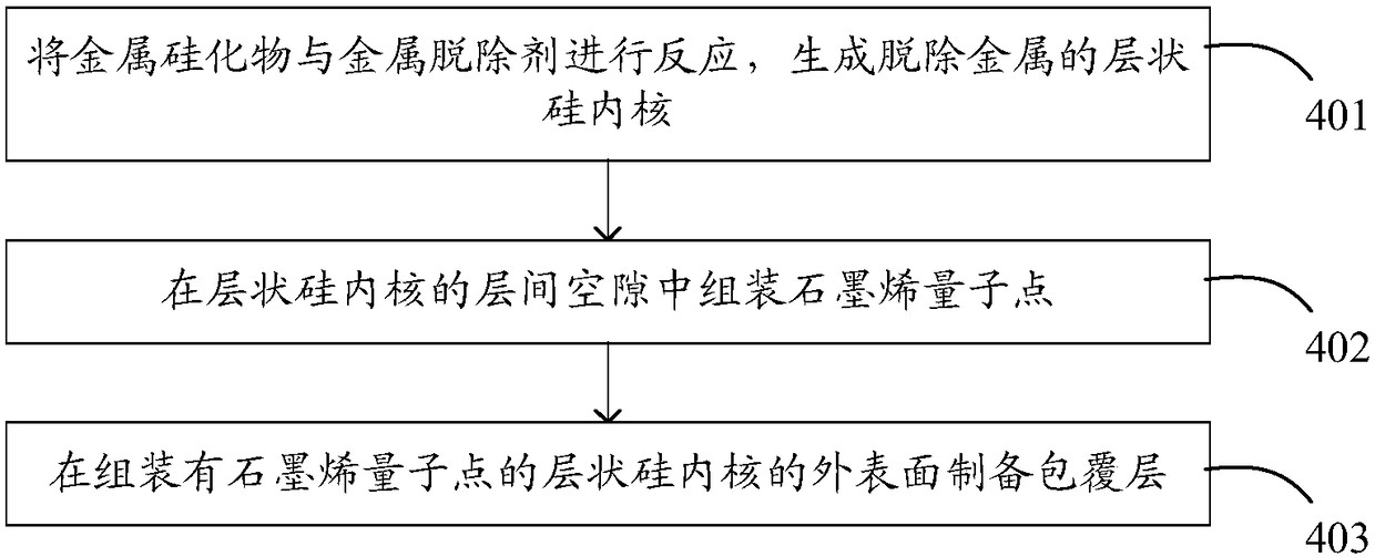
[0040] figure 1 Shown is the schematic flow chart of the method for preparing the electrode material of the present application, including:

[0041] Step 401 , reacting the metal silicide with a metal-removing agent to form a metal-removed layered silicon core. The layered silicon core includes at least two layers of silicon-based materials with interlayer gaps between adjacent two layers of the at least two layers of silicon-based materials, and the silicon-based materials include at least one of silicon or silicon oxides, for example, silicon The base material may be any one of silicon, silicon dioxide, and silicon monoxide, or the silicon-based material may include two of silicon, silicon dioxide, and silicon monoxide, or all three of them.

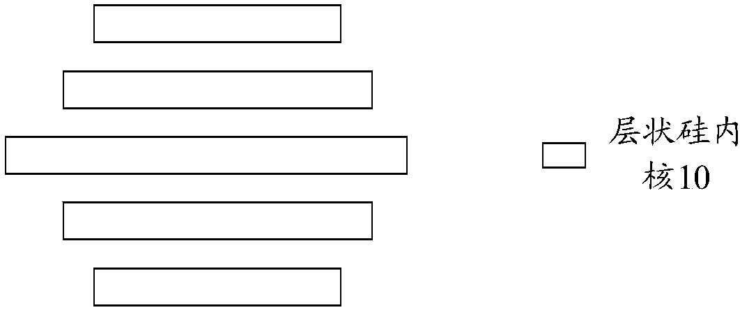
[0042] Figure 2a It is a schematic diagram of the layered silicon core. It should be noted that in the technical solution of the embodiment of the present application, although there is an interlayer gap between two adjacent layers ...

Embodiment 2

[0099] In the method for preparing an electrode material provided in Example 2 of the present application, after the layered silicon core is obtained according to step 401, graphene quantum dots are modified on the outer surface of the layered silicon core, Figure 2f Schematic diagram of the layered silicon core of surface-modified graphene quantum dots. The way of forming graphene quantum dots on the surface of the layered silicon core can be in-situ growth of graphene quantum dots on the surface of the layered silicon core, such as growing graphene quantum dots by CVD process. In addition, it is also possible to migrate the prepared graphene quantum dots to the outer surface of the layered silicon core.

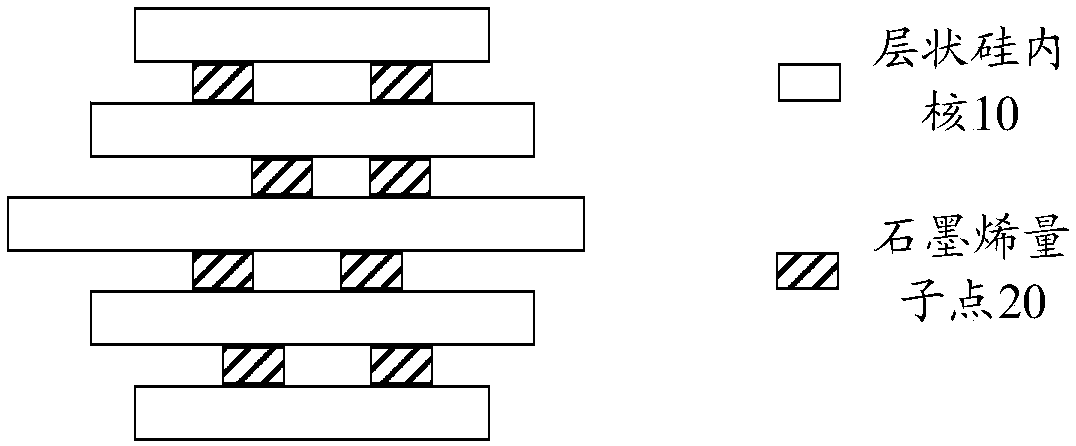
[0100] When the layered silicon core is used as the negative electrode material of the battery, a large number of interlayer gaps in the layered silicon core can slow down the expansion pressure of the negative electrode in the state of intercalating lithium (or other ions...

Embodiment 3

[0103] refer to Figure 2h , in the method for preparing the electrode material provided in Example 3 of the present application, after the layered silicon core is obtained according to step 401, a cladding layer is prepared on the outer surface of the layered silicon core, and the formation implementation has been described in detail in step 403 , which will not be repeated here.

[0104] In the above technical solution, when the layered silicon core is used as the negative electrode material of the battery, a large number of interlayer gaps in the layered silicon core can slow down the expansion pressure of the negative electrode in the state of intercalating lithium (or other ions released by the positive electrode of the battery), reducing the The volume change of the battery negative electrode material during charging and discharging can effectively avoid the pulverization of the battery negative electrode material and improve the service life of the battery negative elec...


PUM

PropertyMeasurementUnit
Sizeaaaaaaaaaa

Abstract

The application provides an electrode material preparation method, an electrode material and a battery, used to solve the problem existing in the prior art that the silicon anode material in the battery can be easily pulverized in a full-embedded state. The electrode material comprises: a layered silicon core and graphene quantum dots; wherein the layered silicon core comprises at least two layersof silicon based material; an interlayer gap between the adjacent two layers of the at least two layers of silicon based material; wherein the silicon based material comprises at least one of siliconor oxide of silicon; and wherein the graphene quantum dots are located in the interlayer gap of the at least two layers of silicon based material.

Description

technical field [0001] The present application relates to the field of material technology, in particular to a method for preparing an electrode material, an electrode material and a battery. Background technique [0002] Lithium-ion batteries usually use graphite as the negative electrode material. The theoretical gram capacity of graphite is 372mAh / g, but the gram capacity of the currently used graphite has exceeded 360mAh / g, which is close to the theoretical limit, and it is difficult to have room for improvement. The energy density of the battery is further improved. [0003] The theoretical gram capacity of silicon is much greater than that of graphite, reaching 4200mAh / g, and it is very promising to be used as a negative electrode material for batteries. However, when the silicon negative electrode is fully intercalated with lithium, the volume expansion is as high as 300%-400%, which will cause the solid electrolyte interface film (solid electrolyte interface, SEI) t...

Claims


Application Information

Patent Timeline
IPC IPC(8): H01M4/583H01M4/38H01M4/36H01M4/1395H01M4/1393
CPCH01M4/1393H01M4/1395H01M4/362H01M4/366H01M4/386H01M4/583H01M4/587H01M10/0525Y02E60/10C23C16/045C23C16/26C23C16/4417H01M2004/027
Inventor 于哲勋李阳兴
Owner HUAWEI TECH CO LTD
Why Eureka
Try Eureka