Compensation method for electric small antenna by operational amplifier

An operational amplifier and electric small antenna technology, applied in the field of antenna compensation, can solve the problems of bandwidth limitation and difficult to break through the frequency bottleneck, and achieve the effect of expanding the bandwidth and making up for the inability to obtain a higher operating frequency.

Inactive Publication Date: 2018-10-16
ZHEJIANG UNIV
View PDF4 Cites 2 Cited by
  • Summary
  • Abstract
  • Description
  • Claims
  • Application Information

AI Technical Summary

Problems solved by technology

At present, many applications are limited by the bandwidth of traditional negative impedance conversion circuits, and only equivalent negative impedance devices within 500MHz can be realized.
Most researchers are devoted to the use of the frequency characteristics of this frequency band, and it is difficult to break through the frequency bottleneck

Method used


Image

  • Compensation method for electric small antenna by operational amplifier
  • Compensation method for electric small antenna by operational amplifier
  • Compensation method for electric small antenna by operational amplifier

Examples


Embodiment

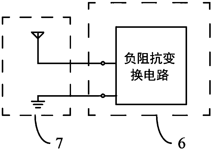
[0037] In order to verify the compensation of this method for electrically small antennas, a monopole antenna fed by a coplanar waveguide is implemented as an electrically small antenna, such as Figure 6 shown. The monopole antenna is fed by the central conductor of the coplanar waveguide, and the conductors on both sides of the coplanar waveguide are used as the ground. The structure is a single-plane structure, and the structure is compact and simple. It is designed as a small-sized antenna with an operating frequency of 300 MHz and an electrical size of about 5 cm for one-tenth of a wavelength. The electrically small antenna is implemented on an FR4 board with a dielectric board thickness of 1 mm, a metal thickness of 0.018 mm, and a relative dielectric constant of 4.2. The final CPW fed monopole antenna as Figure 6 shown.

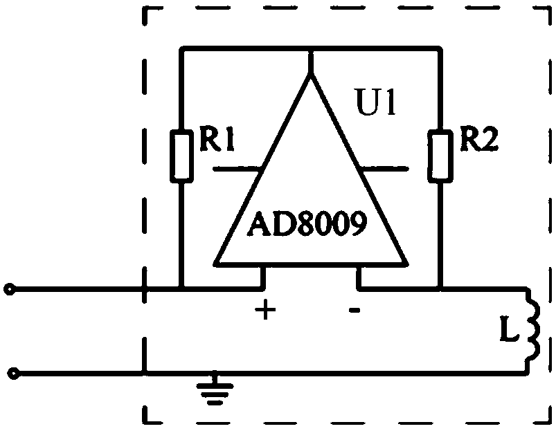
[0038] use figure 2 The circuit structure realizes a negative impedance transformation circuit. Then implemented as Figure 6The shown electri...


PUM


Abstract

The invention discloses a compensation method for an electric small antenna by an operational amplifier. A negative impedance conversion circuit which consists of the operational amplifier is adoptedfor performing dispersion compensation on the electric small antenna; the negative impedance conversion circuit is connected to the electric small antenna in parallel; in the negative impedance conversion circuit, the positive input end of the operational amplifier U1 is connected to the self output end through a resistor R1; the reverse input end of the operational amplifier U1 is connected to the self output end through a resistor R2; and the reverse input end of the operational amplifier U1 is connected with one end of an inductor L while the other end of the inductor L and the positive input end of the operational amplifier U1 are used as the output two ends of the negative impedance conversion circuit. By virtue of the compensation method, broadband matching of the electric small antenna at high frequency is realized, and bandwidth broadening is realized; and dispersion compensation can be performed on an electric small antenna equal-altitude reactance device, so that the shortcoming that relatively high working frequency cannot be obtained in broadband matching of the conventional negative impedance conversion circuit is overcome.

Description

technical field [0001] The invention relates to an antenna compensation method, in particular to a method for compensating an electrically small antenna by using an operational amplifier. Background technique [0002] With the widespread application of advanced communication technologies such as frequency modulation and spread spectrum, the development of large-scale integrated circuits and space technology, and the miniaturization of electronic devices, higher requirements are placed on the miniaturization of communication equipment and system bandwidth. As a key component in communication equipment, the antenna is a converter of electromagnetic energy from the equipment to the space, and its performance directly affects the working quality of the equipment. Therefore, the research on the miniaturization and bandwidth of the antenna has always been a research in this field. hot spot. [0003] In recent years, research results on operational amplifiers have shown that in th...

Claims


Application Information

Patent Timeline
Patent Type & Authority Applications(China)
IPC IPC(8): H01Q23/00
CPCH01Q23/00
Inventor 朱安杰杨婧茹乔闪冉立新
Owner ZHEJIANG UNIV
Why Eureka
Try Eureka