Conversion system, heat dissipation device and wind generating set

A technology for wind turbines and heat dissipation devices, which is applied in the modification of power electronics, output power conversion devices, electrical components, etc., can solve problems such as the inability of the converter to operate, and achieve the effect of reliable heat dissipation and reduction of manufacturing costs.

Active Publication Date: 2018-10-16
BEIJING GOLDWIND SCI & CREATION WINDPOWER EQUIP
7 Cites 2 Cited by

AI-Extracted Technical Summary

Problems solved by technology

Once the cooling system fails, the individual converte...

Method used

By making the radiator directly protrude out of the cabin to be exposed to the external environment, and setting an air duct structure capable of capturing airflow and drainage, in the case of cooling multiple power modules, it is possible to rely on the natural wind from the outside to control the cooling of these power modules. The respective radiators are individually air-cooled, thereby avoiding air mixing, significantly improving the cooling effect of each power module, and ensuring the normal operation of the modules. In addition, a separate cooling system is completely dispensed with, thereby significantly reducing manufacturing costs. In addition, the structure and installation of the cooling device are relatively simple, occupying a small space in the cabin, and can be applied in various suitable places.
In addition, as mentioned above, when the air inlet duct 8 and the air outlet duct 9 are generally arranged along the direction from the windward side of the cabin to the leeward side, as much air flow as possible can be directly blown to the air inlet duct 8 within. In order to further accelerate the flow velocity of the external airflow in the air duct structure, the air inlet duct 8 can also be set tapered along the airflow direction or along the first direction (that is, the direction from the windward side to the leeward side of the cabin), and then The airflow can be made to flow through the radiator 21 faster, and the heat dissipation effect can be improved.
In the provided embodiment, the converter is modified from the original independent converter cabinet to be installed inside the nacelle, thereby eliminating the use of large-sized converter cabinets and fully utilizing the Space. Moreover, the distance between the converter and the generator is significantly shortened, thereby significantly reducing the usage of low-voltage cables between the converter and the generator, and reducing the installation cost of the converter. In addition, by placing the radiators of each power module outside the engine room, the power modules are independently air-cooled by using the natural wind or airflow at high altitudes outside. On the one hand, the cooling of the power modules is effectively realized; ...

Abstract

The invention discloses a conversion system, a heat dissipation device and a wind generating set. The conversion system comprises a plurality of power modules, the power modules are paved inside a cabin of the wind generating seat; a radiator is arranged on each power module; and the conversion system also comprises a heat dissipation device for carrying out heat dissipation on the radiators by using an external air flow. Through the conversion system, the power modules are installed inside the cabin, so that a converter body is omitted, the using amount of cables is reduced, and the heat dissipation of each power module is improved.

Application Domain

Modifications for power electronicsPower conversion systems

Technology Topic

NacelleAirflow +4

Image

  • Conversion system, heat dissipation device and wind generating set
  • Conversion system, heat dissipation device and wind generating set
  • Conversion system, heat dissipation device and wind generating set

Examples

  • Experimental program(1)

Example Embodiment

[0031] In order to enable those skilled in the art to better understand the present invention, specific embodiments of the present invention are described in detail below with reference to the accompanying drawings.
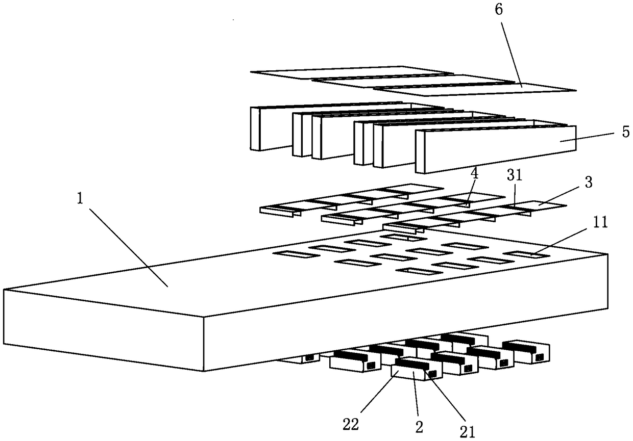
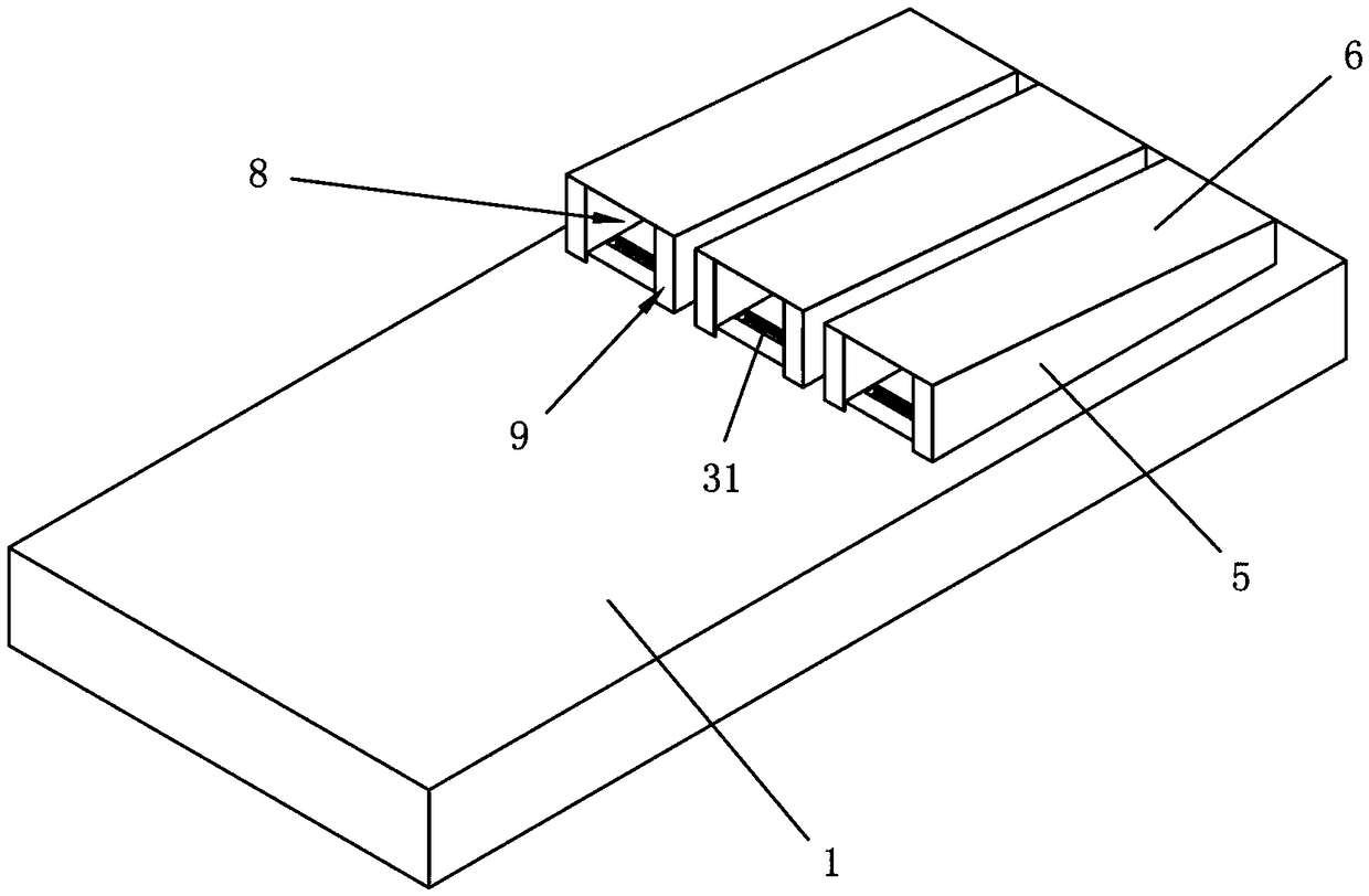
[0032] refer to figure 1 , according to an embodiment of the present invention, a converter system for a wind turbine is provided. The converter system may include a plurality of power modules 2, a heat sink 21 may be provided on each power module 2, and the power modules 2 and the heat sink 21 may be integrally formed as a single component. The power module 2 can be laid flat inside the nacelle of the wind power generator, for example, can be directly installed on the inner wall of the nacelle.
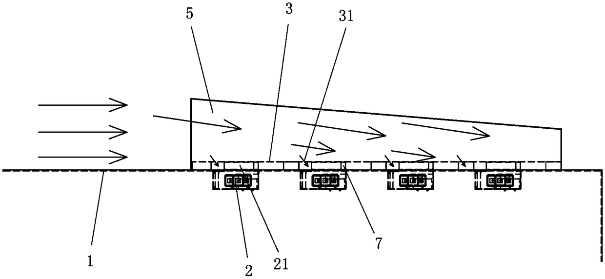
[0033] Usually, for the nacelle of a wind turbine, it has a head and a tail. When the wind turbine is running, the external airflow or wind flows from the head of the nacelle to the tail, that is, the head of the nacelle is the windward side, and the tail for the leeward side. Wheel hubs, generators, gearboxes and various electrical mechanisms are usually installed in the nacelle. The wheel hub is generally installed at the front in the nacelle, and the generator, gearbox and electrical mechanism are installed at the rear of the wheel hub. The rear area of ​​the nacelle where components such as generators are installed generally includes a top, bottom and side panels connected to each other, as well as a stern panel.
[0034] A plurality of power modules 2 can be mounted on the inner wall of the nacelle in a matrix form. For example, the power modules 2 may be divided into 3 groups, each group may include four power modules, and each group of power modules may be arranged in a row. Likewise, the heat sinks 21 are also arranged in a matrix form. In one embodiment, each group of power modules 2 and corresponding heat sinks 21 may be arranged on the nacelle along the first direction. The first direction may be the direction from the head (ie, windward side) to the aft (ie, leeward side) of the nacelle.
[0035] In one embodiment, the power module 2 can be directly suspended on the inner wall of the nacelle using fasteners, and the radiator 21 can protrude outside the nacelle. In order to prevent foreign objects such as external dust or water from entering the interior of the engine room, a sealing member may be installed between the power module 2 and the inner wall of the engine room, so as to realize the sealing of the engine room. The sealing member may include a sealing ring, a sealing ring or a sealing strip and the like for effectively closing the gap between the two, or a return groove structure formed on the contacting or opposing surfaces, and the like.
[0036] The variable flow system provided by the present invention further includes an air duct structure, and the air duct structure can guide the outside air to flow through the radiator 21 and dissipate heat from the radiator 21 . Specifically, the air duct structure can guide the external airflow outside the nacelle along the first direction, and can divide the same airflow into a plurality of branch airflows, and then use these branch airflows to flow through and cool each radiator 21 respectively, so as to realize Independent cooling of power module 2 and heat sink 21 .
[0037] Specifically, the air duct structure may include an air inlet duct 8 and an air outlet duct 9 arranged along the first direction and a plurality of cooling chambers 7 separated from each other, and the air inlet duct 8 and the air outlet duct 9 may be connected with these cooling chambers 7 Connected. A radiator 21 may be arranged in each cooling chamber 7 . The air inlet duct 8 divides the airflow into a plurality of branch airflows along the first direction, and these branch airflows can then flow into each cooling chamber 7 respectively, thereby cooling the radiators 21 in each cooling chamber 7 respectively. The branched air flow after cooling through the radiator 21 is merged into the air outlet duct 9, and then the heat dissipation operation is completed.
[0038] In one embodiment, the power modules 2 may be mounted on the inner walls of the top, side and bottom panels of the nacelle, wherein the side panels are generally vertical panels extending between the top and bottom panels. Therefore, the power module 2 can be cooled directly by the air flow around these plates from the head of the nacelle to the rear of the nacelle. Preferably, the power module 2 can be suspended on the roof of the nacelle, so that the radiator 21 can be vertically protruded upward, and the radiator can capture the upper air flow of the wind turbine and provide a separate parallel air duct for the power module 2 to The individual power modules 2 are cooled independently.
[0039] In the provided embodiment, the converter is modified from the original separate converter cabinet to be installed inside the nacelle, thereby eliminating the use of a large-sized converter cabinet and making full use of the space in the nacelle. In addition, the distance between the converter and the generator is significantly shortened, thereby significantly reducing the usage of low-voltage cables between the converter and the generator, and reducing the installation cost of the converter. In addition, by placing the radiator of each power module outside the nacelle, the power module is independently air-cooled by the natural wind or airflow at a high altitude outside, which effectively realizes the cooling of the power module on the one hand, and avoids the Set up a separate cooling system (including cooling pipes, cooling pumps, coolants and other components), which can significantly reduce costs, and completely avoid the current situation that the converter cannot work normally due to cooling system failures, ensuring variable flow The wind turbine can perform reliable cooling without cooling failures while the wind turbine is running.
[0040] The following describes the heat sink in detail. It should be noted that in addition to the wind turbine, the heat dissipation device can also be used in other suitable cabins. In the following embodiments, an example of installation in a cabin in which there is a flowing outside air flow is described.
[0041] The heat sink may be used to cool any suitable electronic device or device. The heat dissipation device may include a plurality of heat sinks 21 and air duct structures. These radiators 21 may protrude from the side wall 1 of the cabin to the outside of the cabin, and may be arranged in a row from the side wall 1 of the cabin along a first direction, for example, may be along from the windward side of the cabin to the leeward side The directions of the sides are arranged in rows. The number of heat sinks 21 may be at least two. The air duct structure can be generally arranged around the radiator 21, and can guide the outside air flow along the first direction to divide the air flow into a plurality of branch air flows, so that the plurality of branch air flows can respectively flow through the plurality of radiators 21, thereby Exchange heat with the radiator 21 to take away the heat on the radiator 21 .
[0042] The radiator 21 can be connected to a device or device that needs to be cooled. For example, in the following embodiments, the radiator 21 can be integrally provided with the power module 2 to be cooled. On the inner side wall, ie, the power module 2 can be inside the cabin, and the radiator 21 can protrude out of the cabin.
[0043] The installation positions of the power module 2 and the radiator 21 on the cabin may be determined according to actual conditions. For example, the power module 2 and the heat sink 21 may be mounted on the top side wall of the cabin. The side wall mentioned here may refer to any side wall of the cabin, as long as the side wall is the wall enclosing the cabin. A mounting opening 11 may be opened on the side wall 1 (for example, the top side wall) of the cabin, the radiator 21 may pass through the mounting opening 11 and be exposed to the outside of the side wall 1, and the power module 2 may be mounted on the side wall 1 inside. The size of the mounting opening 11 may be set to be slightly larger than the size of the heat sink 21 and only allow the heat sink 21 to pass therethrough.
[0044] For this reason, in order to prevent foreign matter such as external dust, rain, snow, and salt mist from entering the cabin through each installation port 11, a sealing member is further installed between the power module 2 and the inner side wall of the cabin, so as to realize the sealing of the cabin or prevent the outside Foreign objects entered the interior of the cabin. For example, the sealing member may include a sealing ring, a sealing ring or a sealing strip or the like that effectively closes the gap between the two, or a return groove structure formed on the contacting or opposing surfaces, and the like.
[0045] In one embodiment, the sealing ring can be fixed on the inner side wall of the cabin around the installation opening 11 or on the part of the power module 2 that is in contact with the side wall 1 or faces the side wall 1 and is also around the installation opening 11, The sealing between the two is thus achieved from the inside of the compartment. According to other embodiments of the present invention, any other suitable sealing method may also be adopted, as long as there is no entry or exit gap between the power module 2 and the side wall 1 . For example, a sealing ring can be installed directly between the edge of the mounting opening 11 and the heat sink 21 to achieve sealing around the heat sink 21 at the mounting opening 11; or an adhesive can also be used to seal the space between the power module 2 and the side wall 1 The gaps can also be filled.
[0046] When fixing, the power module 2 can be installed and fixed on the side wall 1 of the cabin in any suitable manner, or attached to the inner side wall of the cabin, so as to form a wall-attached structure. For example, the main body portion 22 of the power module 2 can be directly fastened to the side wall 1 by fasteners such as bolts, or can also be installed by any other combination such as adhesive, snap-fit, and tethering. When bolts are used to fasten the power modules 2 to the side walls 1 of the cabin, the assembly of the bolts can be performed from inside or outside the cabin.
[0047] The air duct structure of the heat sink according to the embodiment of the present invention may include an air inlet duct 8 and an air outlet 9 and a plurality of cooling chambers 7 separated from each other, and the cooling chambers 7 may be formed around the radiator 21, that is, in the A radiator 21 is accommodated in each cooling chamber 7 . The air inlet duct 8 can divide the airflow into a plurality of branch airflows along the first direction, and these branch airflows can further flow into the respective cooling chambers 7 and exchange heat with the radiators 21 in the cooling chambers 7, thereby cooling the respective radiators individually twenty one.
[0048] Both the air inlet duct 8 and the air outlet duct 9 may communicate with the plurality of cooling chambers 7 . When the power module 2 needs to be cooled, the external air flow first flows into the air inlet duct 8, and then is divided into a plurality of cooling chambers 7, so that a parallel flow path can be generally formed, and the radiators can be cooled in parallel or through each radiator. After 21, it is merged into the air outlet 9. Therefore, after cooling one radiator 21 , the heated airflow will not flow to the other radiator 21 , thereby preventing airflow mixing and affecting the overall heat dissipation effect.
[0049] In a specific embodiment, the air duct structure may include a layered plate 3, the layered plate 3 may be substantially parallel to the outer sidewall of the cabin, and may be arranged above the plurality of radiators 21, and the arrangement includes directly covering the heat sink on the radiator 21 or at a certain distance above the radiator 21 . The length and width of the layered plate 3 ensure that these power modules 2 can be covered, for example, a row of power modules 2 can be covered. The air inlet duct 8 may be formed on the layered plate 3 .
[0050] A plurality of partitions 4 are fixedly connected between the layered plate 3 and the outer side wall of the cabin, and these partitions 4 may be perpendicular to the outer sidewall of the cabin and the layered plate 3 . The partitions 4 can separate adjacent radiators 21 to form cooling chambers 7 around each radiator 21 or between two adjacent partitions 4, and these cooling chambers 7 are also formed in the layered plates. 3 below. That is to say, partitions 4 are arranged on both the front and rear sides of the radiator 21, and there is a certain distance between the partitions 4 and the radiator 21, so that the cooling chamber 7 has a suitable size, so that enough outside air can flow in into the cooling chamber 7, and sufficiently cool the radiator 21 to achieve the desired cooling effect, and prevent the temperature of the power module 2 from being too high to affect the normal operation.
[0051] As mentioned above, the air inlet duct 8 is formed above the layered plate 3, for this purpose, the air inlet 31 can be opened on the part of the layered plate 3 between the two adjacent partition plates 4, such as image 3 As shown, the airflow flowing into the air inlet duct 8 can flow into the corresponding cooling chamber 7 through each air inlet 31 , thereby cooling the radiator 21 . Further, the air intake 31 may be formed on a portion of the layered plate 3 that is in front of the corresponding heat sink 21 , which portion may be substantially in front of the portion of the layered plate 3 that is located between adjacent two partition plates 4 so that the airflow flowing into the cooling chamber 7 from the air inlet 31 can first flow to the front of the radiator 21 , and then flow from the front of the radiator 21 to the rear of the radiator 21 , thereby taking away the heat of the radiator 21 .
[0052] The air duct structure may further include a plurality of side baffles 5 and an upper cover plate 6 . These side baffles 5 can be perpendicular to and fixed on the outer side wall of the cabin, and can extend along the first direction. Two side baffles 5 can be provided on at least one side of the layered plate 3 along a second direction perpendicular to the first direction, for example, one side baffle can be directly connected to the layered plate 3, and the other side baffle can be directly connected to the layered plate 3. can be moved away from the layered plate 3, such as figure 2 shown. The air outlet duct 9 may be formed between the two side baffles 5 . It should be noted that the side of the layered board 3 described here refers to the side of the layered board 3 extending along the first direction.
[0053] For example, a side baffle can be provided on one side of the power module 2 and the layered plate 3, and this side baffle can be used to close the side of the power module 2 and the cooling chamber 7; The other side can be provided with two side baffles 5, and an air outlet 9 can be formed between the two side baffles 5, and the airflow cooled by the radiator 21 in the cooling chamber 7 flows toward one side to the air outlet. within 9. In this case, the cooling chamber 7 is enclosed by the layered plate 3 , the front and rear partitions 4 , the inner side walls of the cabin and the side baffles 5 on both sides of the layered plate 3 .
[0054] However, if the installation space of the power module 2 is sufficient, two side baffles 5 can also be provided on both sides of the power module 2 and the layered plate 3 , so that an outlet can be formed on both sides of the cooling chamber 7 . In the air duct 9, the airflow cooled by the radiator 21 from the cooling chamber 7 flows toward both sides into the two air outlet ducts 9, which will be further described below based on this example.
[0055] The upper cover 6 can directly cover the side baffle 5 and be fixed to the top of the side baffle 5 . For example, the upper cover plate 6 can be used as a single plate to cover all the side baffles 5 , that is, a plurality of air duct structures can share the same upper cover plate 6 . Alternatively, for each row of power modules 2 or each air duct structure, an upper cover plate 6 may be provided to cover the four side baffles on both sides of the power modules 2 in the same row and the corresponding layered plates 3 5. In this case, the air inlet duct 8 is composed of an upper cover plate 6, a layered plate 3 and two side baffles 5 directly connected with the layered plate 3, and the air outlet duct 9 can be composed of two side baffles 5, a compartment The inner side wall and the upper cover 6 are formed, such as figure 2 shown.
[0056] In addition, the part of the side baffle 5 on the side of the air outlet 9 and below the layered plate 3 can also be provided with an air outlet 51, and the cooling chamber 7 has flowed through and cooled by the radiator 21 to become hot. The air flow can flow into the air outlet duct 9 via the air outlet 51 . For example, the air outlet 51 may be opened on the side baffle 5 directly connected to the layered plate 3 . Preferably, in the case where two air outlet ducts 9 are formed, air outlets 51 can be opened on both side baffles 5 corresponding to (directly connected to the layered plate 3), such as Figure 4 As shown, the airflow in the cooling chamber 7 can quickly flow into the air outlet duct 9 through the air outlet 51 toward both sides, so that the airflow in the cooling chamber 7 can quickly flow through the radiator of the power module 2 and quickly flow into the air outlet. Road 9.
[0057] The specific position of the air outlet 51 is further located on the portion of the side baffle 5 behind the corresponding radiator 21 . Therefore, when dissipating heat, the airflow flows from the air inlet 31 into the cooling chamber 7 and flows to the front of the radiator 21, then quickly flows through the radiator 21 to take away the heat and flows to the rear of the radiator 21, and then passes through the air outlets on both sides. 51 flows to the air outlet 9.
[0058] Therefore, in this embodiment, the layered plate 3 is equivalent to dividing the space above the radiator 21 into two upper and lower layers of air ducts, that is, the air inlet duct 8 and the cooling chamber 7 at the lower layer of the air inlet duct 8, because the airflow is The cooling chamber 7 flows from the front to the rear, therefore, the cooling chamber 7 may also be referred to as a cooling air duct herein. At the same time, these cooling air ducts are connected in parallel with respect to each other, so that independent or parallel cooling of a plurality of power modules 2 can be achieved.
[0059] In addition, as described above, when the air inlet duct 8 and the air outlet duct 9 are generally arranged in the direction from the windward side to the leeward side of the cabin, as much airflow as possible can be directly blown into the air inlet duct 8 . In order to further speed up the flow velocity of the outside air in the air duct structure, the air inlet duct 8 can also be arranged in a tapered manner along the airflow direction or along the first direction (ie, the direction from the windward side of the cabin to the leeward side), so that The airflow can flow through the radiator 21 faster, and the heat dissipation effect can be improved.
[0060] In this case, the side baffle 5 can be in the shape of a trapezoid, and the upper cover plate 6 can be in a certain angle relative to the outer side wall of the cabin, so that the air inlet duct 8 is generally in the shape of a horn in terms of appearance.
[0061]As for the air outlet duct 9 , the two side baffles 5 can be arranged in parallel, so that the cross-sectional areas of the air outlet duct 9 are substantially the same everywhere. Or similar to the air inlet duct 8, by making the two side baffles 5 at a certain angle to each other, the air duct 9 can also be arranged to be tapered along the direction of the air flow, so as to accelerate the air flow out of the cooling chamber 7 and into the cooling chamber 7. into the air outlet 9, and then quickly flow out from the air outlet 9.
[0062] It should be noted that both the air inlet duct 8 and the air outlet duct 9 may be penetrating front and rear, so that the airflow can flow smoothly and quickly in the air duct structure, and the phenomenon of airflow congestion can be avoided.
[0063] For the power modules 2 of the converter, the power modules 2 may be arranged in groups, usually in order to perform a specific function, each group may be distributed in a row and may include two or more power modules 2 . For example, the power modules 2 may be divided into three groups, each group may include four power modules 2, and each group of the power modules 2 may be arranged on the cabin along the above-mentioned first direction. Therefore, for each group of power modules 2, one of the above-mentioned heat dissipation devices can be provided to perform heat dissipation operation.
[0064] By exposing the radiator directly out of the cabin to the external environment, and setting up an air duct structure capable of capturing and diverting airflow, in the case of cooling multiple power modules, it is possible to rely on the external natural wind to dissipate the respective heat dissipation of these power modules. The air-cooling device is individually air-cooled, thereby avoiding airflow mixing, significantly improving the cooling effect of each power module, and ensuring the normal operation of the module. In addition, a separate cooling system is completely eliminated, which can significantly reduce manufacturing costs. In addition, the structure and installation of the heat dissipation device are relatively simple, occupy a small space in the cabin, and can be applied to various suitable places.
[0065] In addition, according to an embodiment of the present invention, a wind power generator set is also provided, the wind power generator set may include the above-mentioned nacelle and a heat dissipation device disposed on the wall of the nacelle, and can achieve similar technical effects, which are not omitted here. Repeat.
[0066] The specific embodiments of the present invention have been described in detail above. Although some embodiments have been shown and described, those skilled in the art should understand that the principles and spirit of the present invention, which are defined in the scope of the claims and their equivalents, are not departed from. Under the circumstances, these embodiments can be modified and perfected, and these modifications and improvements should also fall within the protection scope of the present invention.

PUM

no PUM

Description & Claims & Application Information

We can also present the details of the Description, Claims and Application information to help users get a comprehensive understanding of the technical details of the patent, such as background art, summary of invention, brief description of drawings, description of embodiments, and other original content. On the other hand, users can also determine the specific scope of protection of the technology through the list of claims; as well as understand the changes in the life cycle of the technology with the presentation of the patent timeline. Login to view more.

Similar technology patents

Heat dissipation method for CT machine

InactiveCN103622718AHeat dissipation fastReliable cooling
Owner:QINGDAO ANXIN MEDICAL DEVICES

Current conversion system, heat dissipation apparatus, and wind power generator set

ActiveCN108649773AReliable coolinglow manufacturing cost
Owner:BEIJING GOLDWIND SCI & CREATION WINDPOWER EQUIP

LED lamp with convection heat dissipation function

InactiveCN104728672AReliable coolingmethod science
Owner:安徽正能量光电科技有限公司

Container data center with double refrigerating systems

PendingCN107228442AEnergy savingReliable cooling
Owner:ZHENGZHOU YUNHAI INFORMATION TECH CO LTD

Efficient air cooling structure for converter slag-stopping mechanism

ActiveCN105624362Areliable coolingReliable constant pressure and flow
Owner:MAANSHAN LIER KAIYUAN NEW MATERIAL

Classification and recommendation of technical efficacy words

  • low manufacturing cost
  • Reliable cooling

Exercise equipment

InactiveUS6942605B1low manufacturing costlow price of sale
Owner:SUKHOVITSKY FELIKS

Compliance partitioning in testing of integrated circuits

InactiveUS20080061808A1low manufacturing costgood impedance control
Owner:INNOCONNEX

Inkjet recording apparatus

InactiveUS20050237352A1low manufacturing costfine image quality
Owner:KONICA MINOLTA MEDICAL & GRAPHICS INC

LED Bluetooth music ceiling lamp

InactiveCN104165312AReliable coolingFlexible and convenient control mode
Owner:福建信实节能照明有限公司

First stage turbine vane arrangement

ActiveUS20160153294A1good aerodynamicsreliable cooling
Owner:ANSALDO ENERGIA SWITZERLAND AG

Planar magnetron sputtering target

ActiveCN104404463Aincrease profitreliable cooling
Owner:HOHAI UNIV

Lighting device and projector

ActiveUS20160363845A1reliable cooling
Owner:SEIKO EPSON CORP

Cooling device of draw texturing machine

InactiveCN110284235AGuaranteed cooling effectreliable cooling
Owner:台州市涌星贸易有限公司
Why Eureka
Try Eureka