U rib plate unit assembling and welding method

A welding method and rib technology, applied in welding accessories, welding equipment, auxiliary welding equipment, etc., can solve the problems of easy slag inclusion in the welding seam, deflection of the entire U-rib, low work efficiency, etc., to eliminate welding quality problems and ensure Assembly accuracy and the effect of improving welding quality

Inactive Publication Date: 2018-10-19
WUHAN LIXIN AUTOMATION TECH CO LTD
View PDF6 Cites 3 Cited by
  • Summary
  • Abstract
  • Description
  • Claims
  • Application Information

AI Technical Summary

Problems solved by technology

During the formal welding construction, the fixing method of segmented positioning welding is adopted. This fixing method is prone to deflection of the entire U rib, and the positioning accuracy is not high; at the same time, in order to fix the U rib, each side of each U rib, A small piece of tack weld is used for temporary connection every interval of 500-600mm. The length of tack weld is about 50mm, which has the characteristics of short length, small welding feet, large quantity, and low attention in manufact

Method used


Image

  • U rib plate unit assembling and welding method
  • U rib plate unit assembling and welding method

Examples


Embodiment Construction

[0031] The principles and features of the present invention are described below in conjunction with the accompanying drawings, and the examples given are only used to explain the present invention, and are not intended to limit the scope of the present invention.

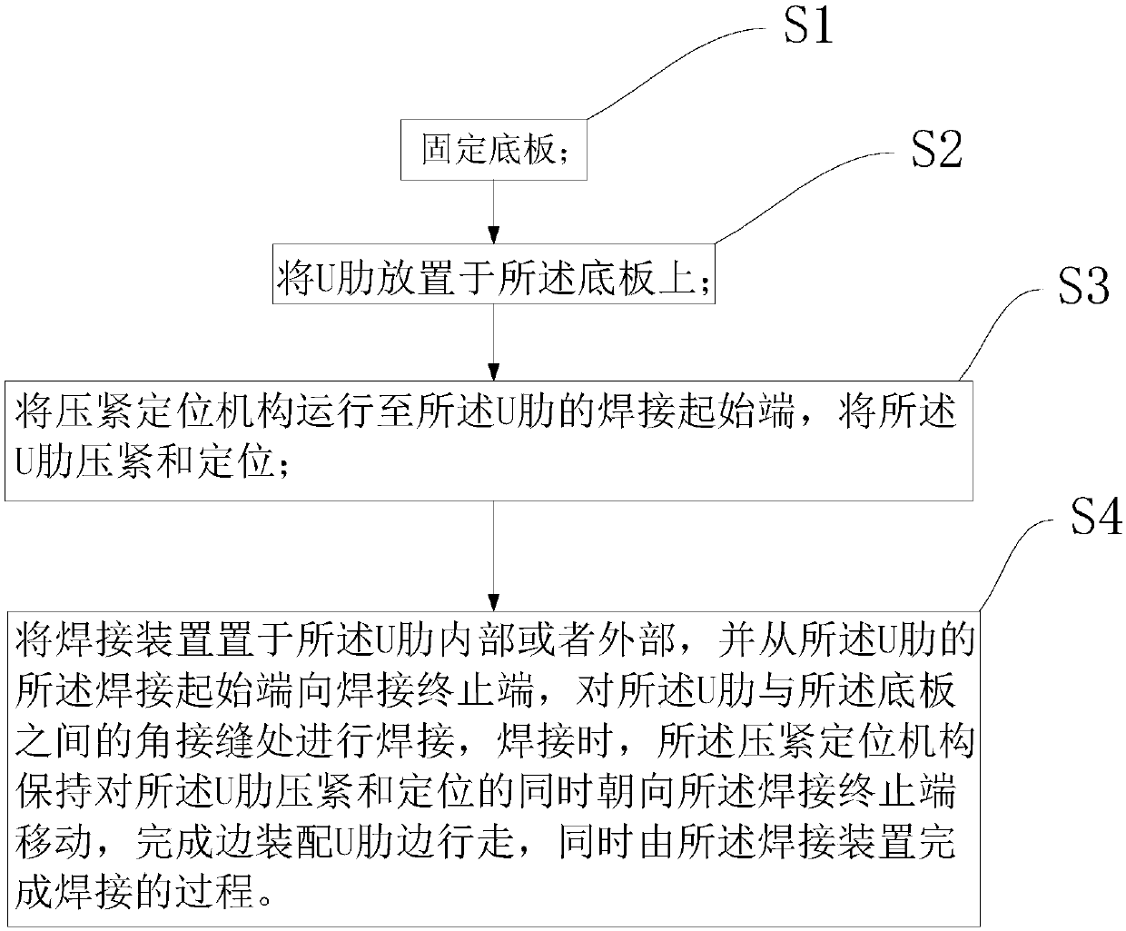
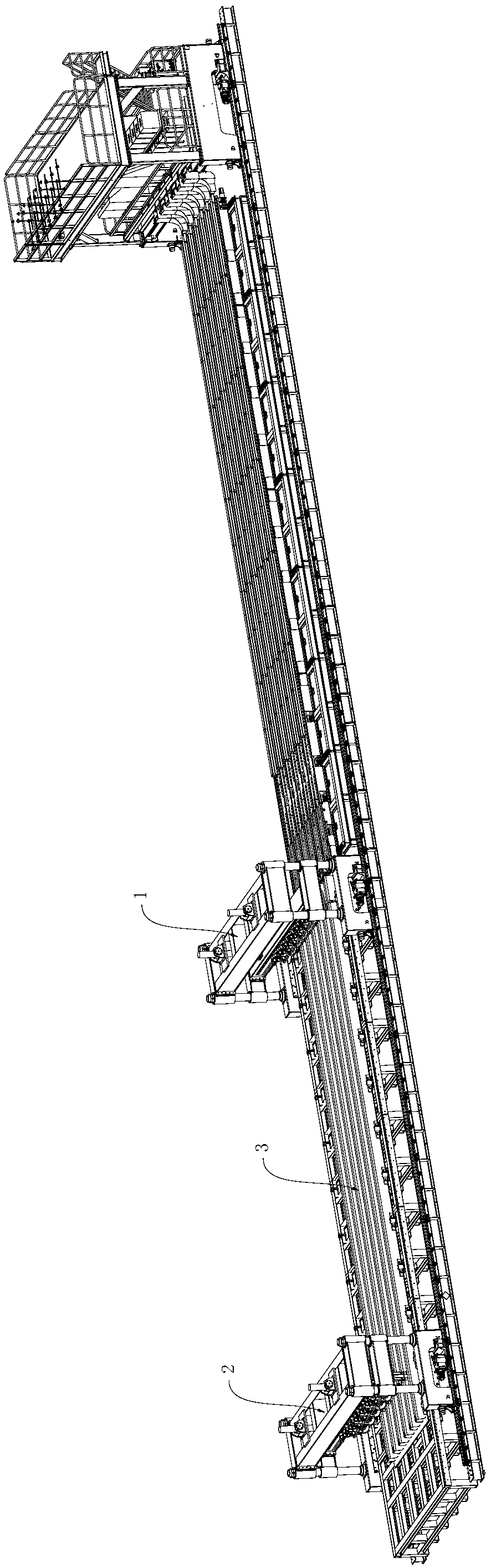
[0032] Please refer to figure 1 and figure 2 , figure 1 A flow chart of a specific embodiment of the welding method of the U-rib unit provided by the present invention; figure 2 It is a schematic diagram of a welding system corresponding to a specific embodiment of the welding method of the U-rib unit provided by the present invention.

[0033] In the specific implementation of the method for assembling and welding a U-rib unit disclosed in the present invention, please refer to figure 1 , the method includes the following steps:

[0034] S1, fix the bottom plate; generally, the bottom plate can be placed on the workbench,

[0035] S2, placing the U-rib on the base plate; generally, mark the base plate in adv...


PUM


Abstract

The embodiment of the invention discloses a U rib plate unit assembling and welding method. The method comprises the following steps of S1, fixing a base plate; S2, putting U ribs onto the base plate;S3, operating pressing and positioning mechanisms to the welding start ends of the U ribs to press and position the U ribs; and S4, putting a welding device inside or outside the U ribs to conduct welding at angle joints between the U ribs and the base plate from the welding start ends of the U ribs to the welding terminal ends of the U ribs, wherein in the welding process, the pressing and positioning mechanisms move to the welding terminal ends to complete assembling of the U ribs, moving and welding at the same time while maintaining pressing and positioning on the U ribs. Through the unitassembling and welding method provided by the invention, the assembly accuracy of the U ribs can be ensured; moreover, except positioning welding required during conventional assembling of the U ribs, the welding quality problem caused by positioned welding is eliminated, the welding quality is improved, and the production efficiency is improved.

Description

technical field [0001] The invention relates to the field of welding technology, in particular to a method for assembling and welding a U-rib unit. Background technique [0002] The steel box girder is an important part of the load-bearing structure of the bridge. The steel box girder is generally an orthotropic steel bridge deck, which is mainly used to provide support and avoid bridge deformation. The steel box girder generally includes structures such as a top plate and a bottom plate, and the top plate and the bottom plate are generally welded by U ribs and the bottom plate. [0003] At present, orthotropic steel bridge decks are widely used in the manufacture of long-span bridges. Both the roof and the bottom plate of the bridge adopt this structure. The orthotropic steel bridge decks are welded by U ribs and the bottom plate. The manufacturing methods are as follows: First, several U-ribs with a length of about 12 meters (not limited) are assembled manually or mechani...

Claims


Application Information

Patent Timeline
IPC IPC(8): B23K37/04B23P19/00B23K9/32
CPCB23K37/04B23K9/32B23K37/0443B23P19/00
Inventor 高兴舒先庆陈积里
Owner WUHAN LIXIN AUTOMATION TECH CO LTD
Why Eureka
Try Eureka