
Radial stator core structure, bearing stator and hybrid radial magnetic bearing

A technology of stator iron core and bearing stator, applied in the field of bearings, can solve the problems of difficult assembly, difficult to accurately control the cooling and retraction of radial rings, low assembly efficiency, etc., and achieves the improvement of electromagnetic utilization rate and bearing capacity, and the success of improving rate and product qualification rate, avoiding the effect of difficult assembly

Active Publication Date: 2018-10-19
GREE ELECTRIC APPLIANCES INC
View PDF7 Cites 3 Cited by
  • Summary
  • Abstract
  • Description
  • Claims
  • Application Information

AI Technical Summary

Problems solved by technology

[0006] 1. Thermal assembly is used between the radial ring and the radial stator core in the prior art, which is difficult to assemble and has low assembly efficiency;
[0007] 2. During the hot assembly process of the radial ring and the radial stator core in the prior art, due to insufficient heating of the parts or environmental influences, it is easy to cause thermal assembly failure, low product qualification rate, and high production cost;
[0008] 3. During the thermal assembly process of the radial ring and the radial stator core in the prior art, the cooling shrinkage of the radial ring is difficult to accurately control, and the accuracy after installation cannot be guaranteed;
[0009] 4. The radial stator core winding slots in the prior art are easy to reach magnetic saturation, and the electromagnetic utilization rate and carrying capacity of the bearing are therefore greatly limited

Method used


Image

  • Radial stator core structure, bearing stator and hybrid radial magnetic bearing
  • Radial stator core structure, bearing stator and hybrid radial magnetic bearing
  • Radial stator core structure, bearing stator and hybrid radial magnetic bearing

Examples


Embodiment Construction

[0041] In order to make the purpose, technical solution and advantages of the present invention clearer, the technical solution of the present invention will be described in detail below. Apparently, the described embodiments are only some of the embodiments of the present invention, but not all of them.

[0042] Accordingly, the following detailed description of the embodiments of the invention provided in the accompanying drawings is not intended to limit the scope of the claimed invention, but merely represents selected embodiments of the invention. Based on the embodiments of the present invention, all other implementations obtained by persons of ordinary skill in the art without making creative efforts fall within the protection scope of the present invention.

[0043] It should be noted that like numerals and letters denote similar items in the following figures, therefore, once an item is defined in one figure, it does not require further definition and explanation in s...


PUM


Abstract

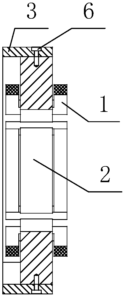
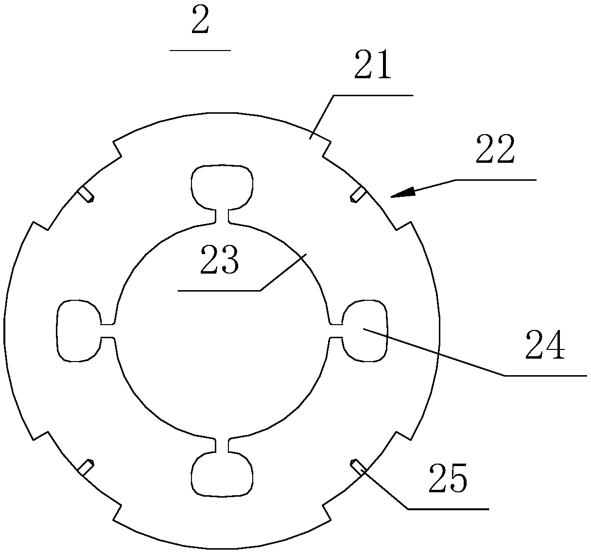
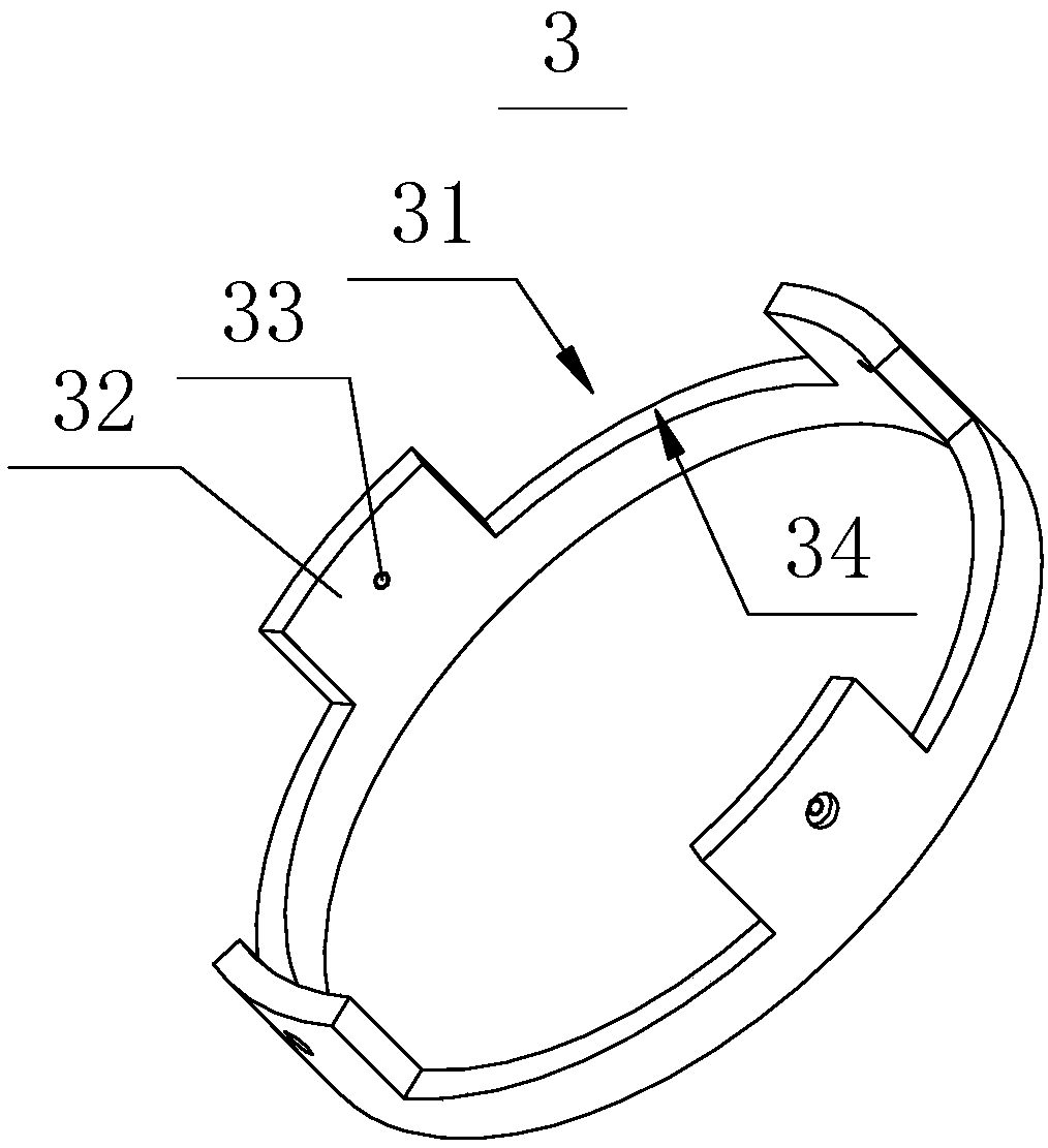
The invention provides a radial stator core structure which comprises a radial stator core and a radial ring connected together, wherein the inner ring of the radial stator core is provided with a wire winding groove; a protruding part corresponding to the wire winding groove is arranged on the outer circumferential wall of the radial stator core; and a groove part in transition fit with the protruding part is arranged on the radial ring. The invention further provides a hybrid radial magnetic bearing which comprises a rotor and a bearing stator, wherein the rotor is coaxially arranged in thebearing stator. Compared with the prior art, the magnetic conductive area of the radial stator core is increased on the condition that the boundary dimension is not increased, and the problem in the prior art that magnetic saturation can be reached easily at the wire winding groove of the radial stator core is solved, so that the electromagnetism utilization ratio and the bearing capacity of the bearing are increased and improved. The radial stator core structure can further optimize the assembling technology to increase the assembling success rate and product percent of pass.

Description

technical field [0001] The invention relates to the technical field of bearings, in particular to a radial stator core structure, a bearing stator and a hybrid radial magnetic suspension bearing. Background technique [0002] Magnetic suspension bearing refers to a high-performance electromechanical integrated bearing that uses electromagnetic force to stably suspend the supported part in space, so that there is no mechanical contact between the supporting part and the supported part. The hybrid radial magnetic bearing is a combined magnetic bearing system formed on the basis of active magnetic bearings, passive magnetic bearings and other auxiliary support and stabilizing structures. It uses the magnetic field generated by the permanent magnet to replace the static bias magnetic field of the electromagnet. , can significantly reduce the ampere-turns of the electromagnet, reduce the volume of the magnetic bearing, reduce power consumption, and increase the carrying capacity....

Claims


Application Information

Patent Timeline
Patent Type & Authority Applications(China)
IPC IPC(8): F16C32/04
CPCF16C32/044
Inventor 邓明星张小波张芳龚高张超苏久展李欣董如昊王飞刘鹏辉
Owner GREE ELECTRIC APPLIANCES INC
Learn More