Wet-type parking brake and engineering machinery
A technology of parking brakes and brakes, which is applied in the direction of brake actuators, mechanical equipment, gear transmission mechanisms, etc., can solve the problems of easy wear of seals, dry grinding of dynamic sealing surfaces, delays in braking and opening processes, etc., to achieve The effect of avoiding friction plate wear, high reliability, and shortening response time
- Summary
- Abstract
- Description
- Claims
- Application Information
AI Technical Summary
Problems solved by technology
Method used
Image

Examples
Embodiment 1
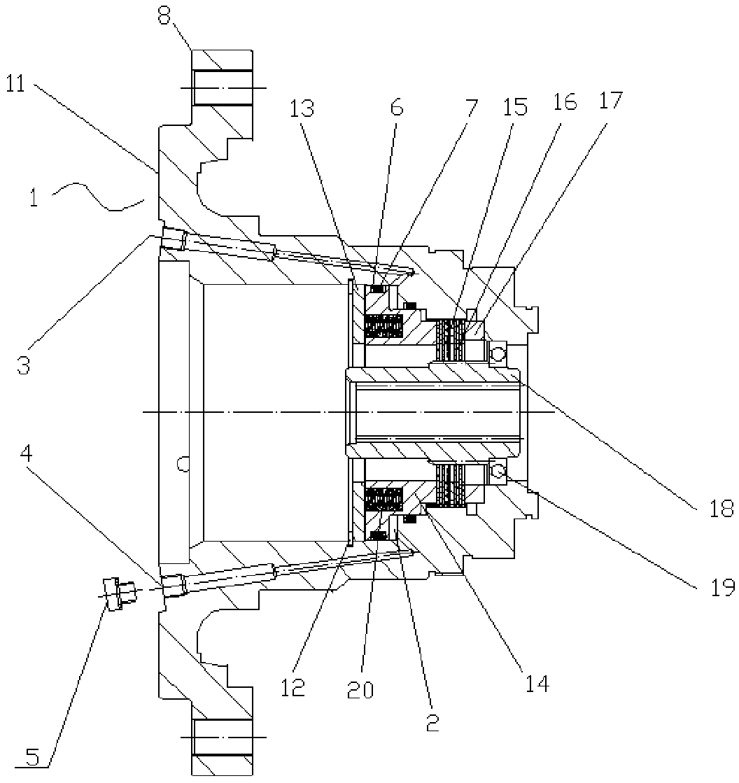
[0033] figure 1 A schematic structural view of the wet parking brake provided in Embodiment 1 of the present invention; figure 1 As shown, the wet parking brake provided by Embodiment 1 of the present invention includes a brake body 1, and the brake body 1 is provided with a brake oil passage 3 communicating with the oil chamber 2, and the brake body 1 is also provided with a The auxiliary oil passage 4 communicated with the oil chamber 2 .
[0034] The method of discharging the air in the oil chamber 2 in this application is as follows: open the brake oil passage 3 and the auxiliary oil passage 4 to make the upper and lower oil ports of the oil chamber 2 communicate with the outside world, inject hydraulic oil into the oil chamber 2 through the auxiliary oil passage 4, and then As the liquid level rises, the air inside the oil chamber 2 is discharged from the brake oil passage 3 until hydraulic oil is discharged from the brake oil passage 3.
Embodiment 2
[0036] The wet parking brake provided in the second embodiment is a further improvement on the wet parking brake provided in the first embodiment. figure 1 On the basis of the above, the wet parking brake provided in the second embodiment includes a brake body 1, the brake body 1 is provided with a brake oil passage 3 communicating with the oil chamber 2, and the brake body 1 is also provided with a The auxiliary oil passage 4 communicated with the oil chamber 2 .
[0037] The method of discharging the air in the oil chamber 2 in this application is as follows: open the brake oil passage 3 and the auxiliary oil passage 4 to make the upper and lower oil ports of the oil chamber 2 communicate with the outside world, inject hydraulic oil into the oil chamber 2 through the auxiliary oil passage 4, and then As the liquid level rises, the air inside the oil chamber 2 is discharged from the brake oil passage 3 until hydraulic oil is discharged from the brake oil passage 3.
[0038] ...
Embodiment 3
[0040] The wet parking brake provided in the third part of this embodiment is a further improvement on the wet parking brake provided in the first embodiment. figure 1 On the basis of the above, the wet parking brake provided in the third embodiment includes a brake body 1, the brake body 1 is provided with a brake oil passage 3 communicating with the oil chamber 2, and the brake body 1 is also provided with a The auxiliary oil passage 4 communicated with the oil chamber 2 .
[0041] The method of discharging the air in the oil chamber 2 in this application is as follows: open the brake oil passage 3 and the auxiliary oil passage 4 to make the upper and lower oil ports of the oil chamber 2 communicate with the outside world, inject hydraulic oil into the oil chamber 2 through the auxiliary oil passage 4, and then As the liquid level rises, the air inside the oil chamber 2 is discharged from the brake oil passage 3 until hydraulic oil is discharged from the brake oil passage 3....
PUM
 Abstract
Description
Claims
Application Information
 - R&D Engineer
- R&D Manager
- IP Professional
- Industry Leading Data Capabilities
- Powerful AI technology
- Patent DNA Extraction
Browse by: Latest US Patents, China's latest patents, Technical Efficacy Thesaurus, Application Domain, Technology Topic.
© 2024 PatSnap. All rights reserved.Legal|Privacy policy|Modern Slavery Act Transparency Statement|Sitemap