
Spray drying system using fuel gas exhaust and spray drying method

A drying system and exhaust gas technology, applied in the direction of drying solid materials, drying gas arrangement, heating to dry solid materials, etc., can solve the problems that the temperature cannot fully match the heat requirements of the spray drying tower, affect the efficiency of material drying, and large evaporation

Pending Publication Date: 2018-10-19
上海力顺燃机科技有限公司
View PDF12 Cites 2 Cited by
  • Summary
  • Abstract
  • Description
  • Claims
  • Application Information

AI Technical Summary

Problems solved by technology

[0003] According to the investigation and research, it is found that in the ceramic industry, the evaporation capacity of the existing spray drying tower is relatively large, and the heat and temperature emitted by the exhaust gas of the gas turbine cannot fully match the heat requirements of the spray drying tower at full load, which requires an increase in combustion. Compensation for heat and temperature by afterburning device
[0004] For the prior art, the gas turbine tail gas is the main heat source of the spray drying tower, and the fuel (natural gas) in the burner supplementary combustion device is burned with the gas turbine tail gas as the oxygen source (about 15% oxygen content of the gas turbine tail gas) , it only plays the role of supplementary heat source. Once the gas turbine fails, the system (including the spray drying tower at the rear end) will all be shut down, which seriously affects the efficiency of material drying

Method used


Image

  • Spray drying system using fuel gas exhaust and spray drying method

Examples


Embodiment Construction

[0028] In order to more clearly illustrate the embodiments of the present invention or the technical solutions in the prior art, the specific implementation manners of the present invention will be described below with reference to the accompanying drawings. Obviously, the accompanying drawings in the following description are only some embodiments of the present invention, and those skilled in the art can obtain other accompanying drawings based on these drawings and obtain other implementations.

[0029] In order to make the drawing concise, the parts related to the present invention are only schematically shown in each drawing, and they do not represent the actual structure of the product.

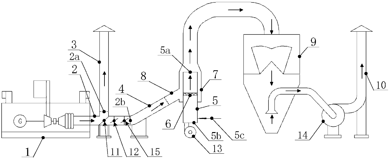
[0030] Please refer to figure 1 , figure 1 It is a schematic structural diagram of a spray drying system using gas tail gas in an embodiment of the present invention.

[0031] The invention provides a spray drying system using gas tail gas, which is used to realize the spray drying o...


PUM


Abstract

The invention provides a spray drying system using fuel gas exhaust and a spray drying method. The spray drying system comprises a gas turbine generator set and a combustion temperature increasing system, the gas turbine generator set and the combustion temperature increasing system are coupled together through a tee joint and other parts, and thus, the spray drying system has three operation modes, specifically, the gas turbine generator set and the combustion temperature increasing system cooperatively provide heat energy for a drying tower, or the combustion temperature increasing system directly provides heat energy, or the spraying amount of thinner is decreased. According to the spray drying system using the fuel gas exhaust and the spray drying method, the combustion temperature increasing system is additionally arranged, can serve as a main heat source to provide the heat energy for the drying tower and can also serve as an auxiliary heat source to cooperate with the gas turbine generator set for usage; the working modes are diversified, meanwhile, the operation reliability of the system is improved, even though some devices break down and stop, other systems can still provide heat energy, and the effect that the spray drying system is operated continuously and stably is ensured.

Description

technical field [0001] The invention relates to the technical field of equipment related to material drying, and more specifically relates to a spray drying system using gas tail gas and a spray drying method. Background technique [0002] Spray drying is a method of systematic technology applied to material drying. The working process of spray drying is as follows: the thinner is atomized in the drying room and then sprayed out. The sprayed atomized thinner is in contact with hot air, and the moisture in the thinner will quickly vaporize, so that a dry product can be obtained. Spray drying can directly dry solutions and emulsions into powder or granular products, which can save evaporation, crushing and other processes. [0003] According to the investigation and research, it is found that in the ceramic industry, the evaporation of the existing spray drying tower is relatively large, and the heat and temperature emitted by the exhaust gas of the gas turbine cannot fully m...

Claims


Application Information

Patent Timeline
IPC IPC(8): F26B3/12F26B21/00F26B23/02
CPCF26B3/12F26B21/001F26B21/004F26B23/02
Inventor 林玉珍张耀冬何晓东章海东
Owner 上海力顺燃机科技有限公司
Learn More