Lithium battery centrifugation liquid injection device

A liquid injection device and lithium battery technology, which is applied to battery pack components, circuits, electrical components, etc., can solve the problems of reducing liquid injection efficiency, electrolyte waste, and capacity reduction, so as to improve liquid injection efficiency and save manufacturing costs , save the effect of wiping the station

Active Publication Date: 2018-10-19
HEFEI GUOXUAN HIGH TECH POWER ENERGY
View PDF4 Cites 7 Cited by
  • Summary
  • Abstract
  • Description
  • Claims
  • Application Information

AI Technical Summary

Problems solved by technology

[0002] In the production process of lithium-ion batteries, the electrolyte is usually injected into the battery, and then the battery is left to stand for a period of time after the injection, so that the electrolyte can fully infiltrate the pole pieces. If the infiltration is not sufficient, it may cause black spots on the interface , the internal resistance increases and the capacity decreases, which directly leads to the reduction of battery life
[0003] Moreover, in the traditional technology, the battery after liquid injection is prone to residual electrolyte in the liquid injection hole, and the crystallization of the electrolyte will affect the sealing of the rear end liquid injection hole
For this reason, a liquid injection hole wiping device is often added after liquid injection, and non-woven fabrics are used to absorb the electrolyte. On the one hand, the efficiency of liquid injection is reduced, and on the other hand, the electrolyte is wasted.

Method used


Image

  • Lithium battery centrifugation liquid injection device
  • Lithium battery centrifugation liquid injection device

Examples


Embodiment Construction

[0017] The following will clearly and completely describe the technical solutions in the embodiments of the present invention with reference to the accompanying drawings in the embodiments of the present invention. Obviously, the described embodiments are only some, not all, embodiments of the present invention. Based on the embodiments of the present invention, all other embodiments obtained by persons of ordinary skill in the art without making creative efforts belong to the protection scope of the present invention.

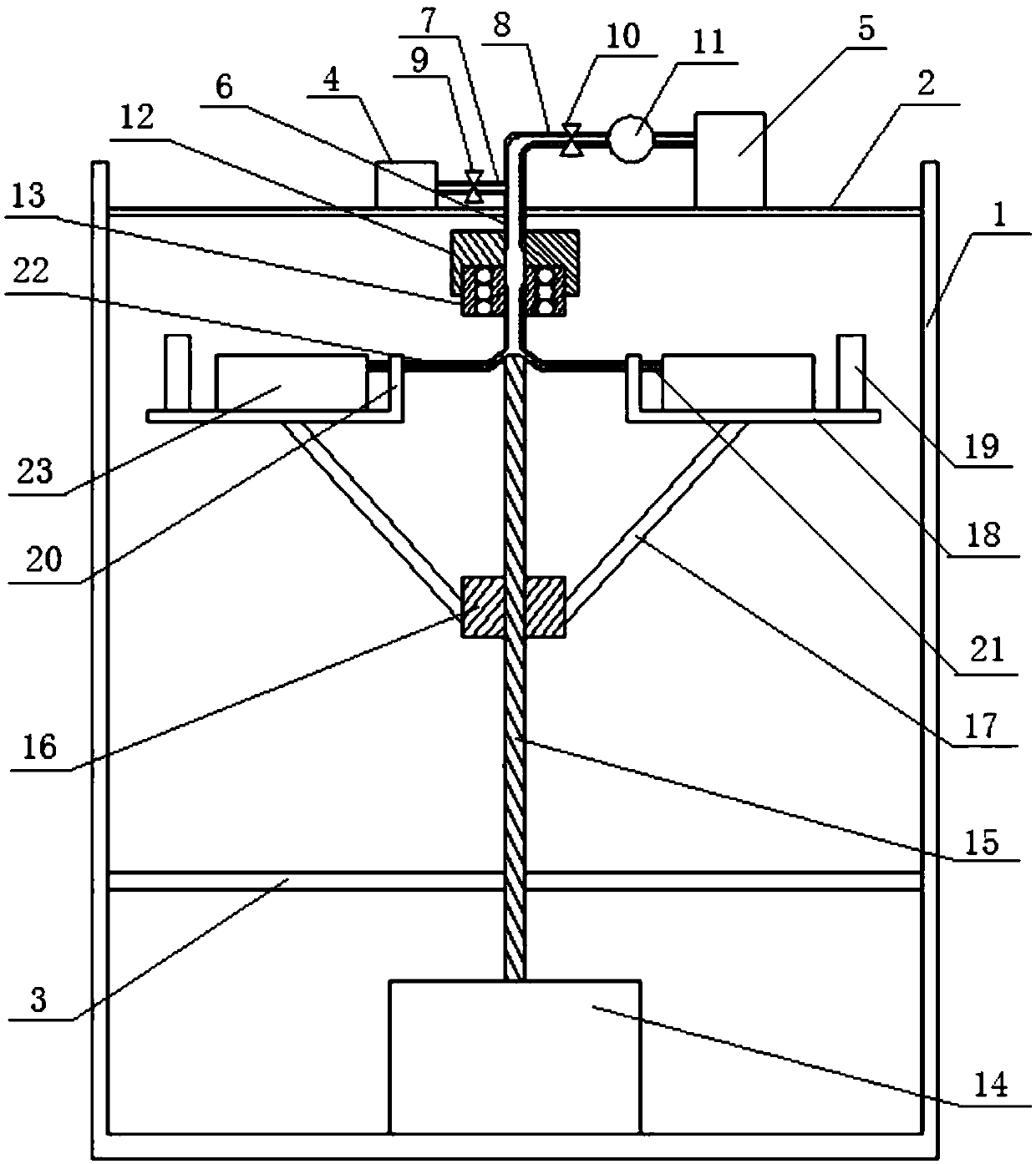
[0018] See figure 1 , a lithium battery centrifugal liquid injection device, including a housing 1, an upper horizontal mounting plate 2 and a lower horizontal mounting plate 3 fixedly arranged in the housing 1, and a liquid supply assembly and a connecting assembly arranged in the housing 1 and centrifugal components;

[0019] The liquid supply assembly includes a vacuum pump 4 and a liquid injection pump 5 arranged on the upper horizontal mounting plate 2, ...


PUM


Abstract

The invention discloses a lithium battery centrifugation liquid injection device. The lithium battery centrifugation liquid injection device comprises a housing, and a liquid supply assembly, a connecting assembly, and a centrifugation assembly which are arranged in the housing; the liquid supply assembly comprises a vacuum pump and a liquid injection pump which are communicated with a liquid supply main pipeline; the centrifugation assembly comprises a driving motor, and a plurality of battery liquid injection mounting racks which are connected with an output shaft of the driving motor through hinge joint; the top of the output shaft of the driving motor is designed to be a tubular structure; the connecting assembly is used for communicating the liquid supply main pipeline with the top ofthe output shaft of the driving motor. In applications, under centrifugal force action, electrolyte is introduced into batteries, electrode plate infiltration is accelerated, and residue of electrolyte in liquid injection hole is not easily left, so that an electrolyte wiping step is avoided, and working efficiency is increased effectively.

Description

technical field [0001] The invention relates to the field of liquid injection for lithium batteries, in particular to a centrifugal liquid injection device for lithium batteries. Background technique [0002] In the production process of lithium-ion batteries, the electrolyte is usually injected into the battery, and then the battery is left to stand for a period of time after the injection, so that the electrolyte can fully infiltrate the pole pieces. If the infiltration is not sufficient, it may cause black spots on the interface , the internal resistance increases and the capacity decreases, which directly leads to the reduction of battery life. [0003] Moreover, in the traditional technology, the battery after liquid injection is prone to residual electrolyte in the liquid injection hole, and the crystallization of the electrolyte will affect the sealing of the liquid injection hole at the rear end. For this reason, a liquid injection hole wiping device is often added ...

Claims


Application Information

Patent Timeline
Patent Type & Authority Applications(China)
IPC IPC(8): H01M2/36H01M50/609
CPCH01M50/60Y02E60/10
Inventor 高冲王晨旭程辉
Owner HEFEI GUOXUAN HIGH TECH POWER ENERGY
Why Eureka
Try Eureka