Eureka AIR delivers breakthrough ideas for toughest innovation challenges, trusted by R&D personnel around the world.

Permanent magnet synchronous motor for guide bar-salient pole hybrid elevator

A permanent magnet synchronous and hybrid technology, applied to synchronous motors with stationary armatures and rotating magnets, synchronous machines, electric components, etc., can solve the problems of easy serious damage to the rotor, increased processing costs, and difficult installation and maintenance. Achieve the effects of avoiding excessive magnetic flux leakage coefficient, reducing processing difficulty and reducing installation requirements

Pending Publication Date: 2018-10-19
JIANGNAN UNIV
View PDF0 Cites 0 Cited by
  • Summary
  • Abstract
  • Description
  • Claims
  • Application Information

AI Technical Summary

Problems solved by technology

[0006] (1) The permanent magnet is inside the iron core, which generates a lot of heat during operation, which is easy to seriously damage the rotor, and is suitable for cold conditions
[0007] (2) The permanent magnet is inside the silicon steel, which is relatively safe in terms of safety, but it also faces difficulties in installation and maintenance
[0011] The air-gap flux density is very complex and difficult to calculate.
[0012] (3) Difficult to install, special tools are needed for installation, and it is easy to fly out.
[0015] (2) This structure cannot simply start the motor, it is necessary to arrange the permanent magnets to form a certain angle with the axis of the rotating shaft. This increases the processing cost to a certain extent
[0016] (3) Because the permanent magnet is on the surface of the rotor, it is easy to install, maintain and replace, but it is also easy to fly out, which requires high adhesives.

Method used


Image

  • Permanent magnet synchronous motor for guide bar-salient pole hybrid elevator
  • Permanent magnet synchronous motor for guide bar-salient pole hybrid elevator
  • Permanent magnet synchronous motor for guide bar-salient pole hybrid elevator

Examples


Embodiment Construction

[0032] The following will clearly and completely describe the technical solutions in the embodiments of the present invention with reference to the accompanying drawings in the embodiments of the present invention. Obviously, the described embodiments are only some, not all, embodiments of the present invention. Based on the embodiments of the present invention, all other embodiments obtained by persons of ordinary skill in the art without making creative efforts belong to the protection scope of the present invention.

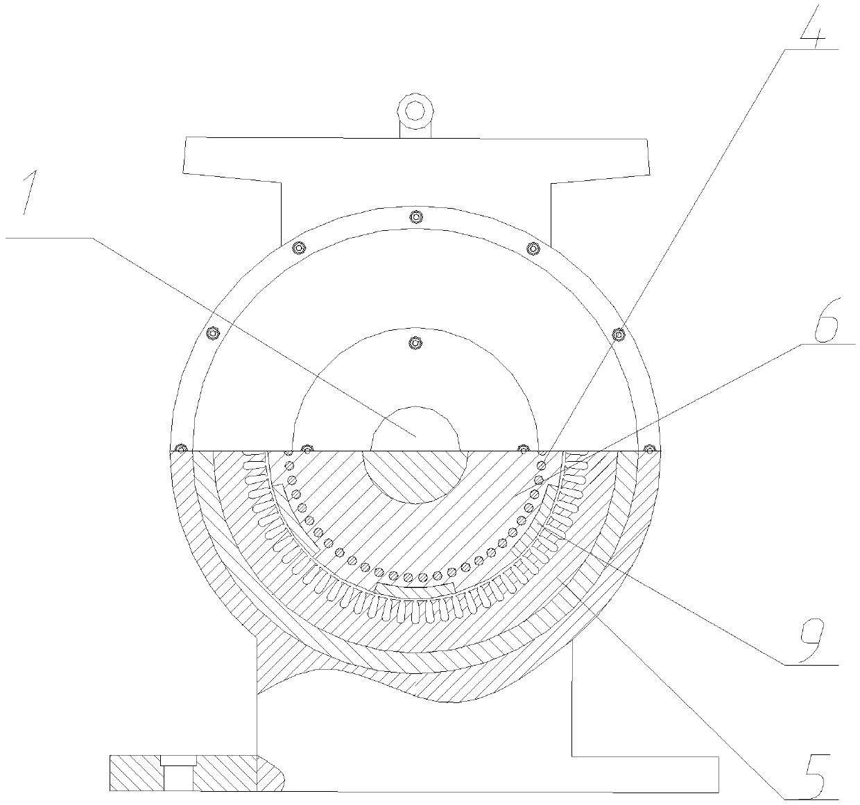
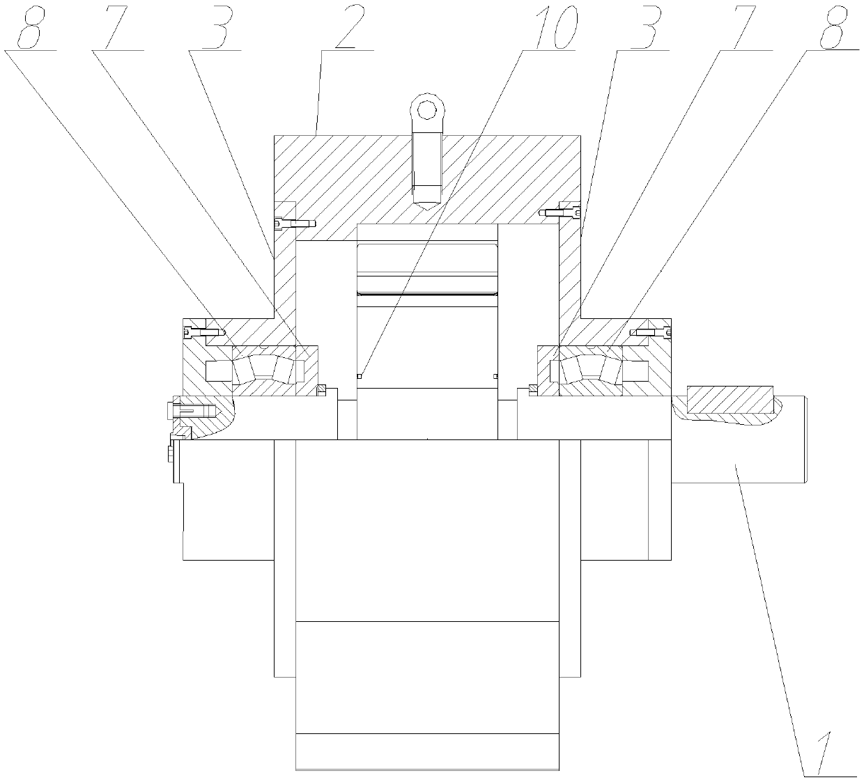
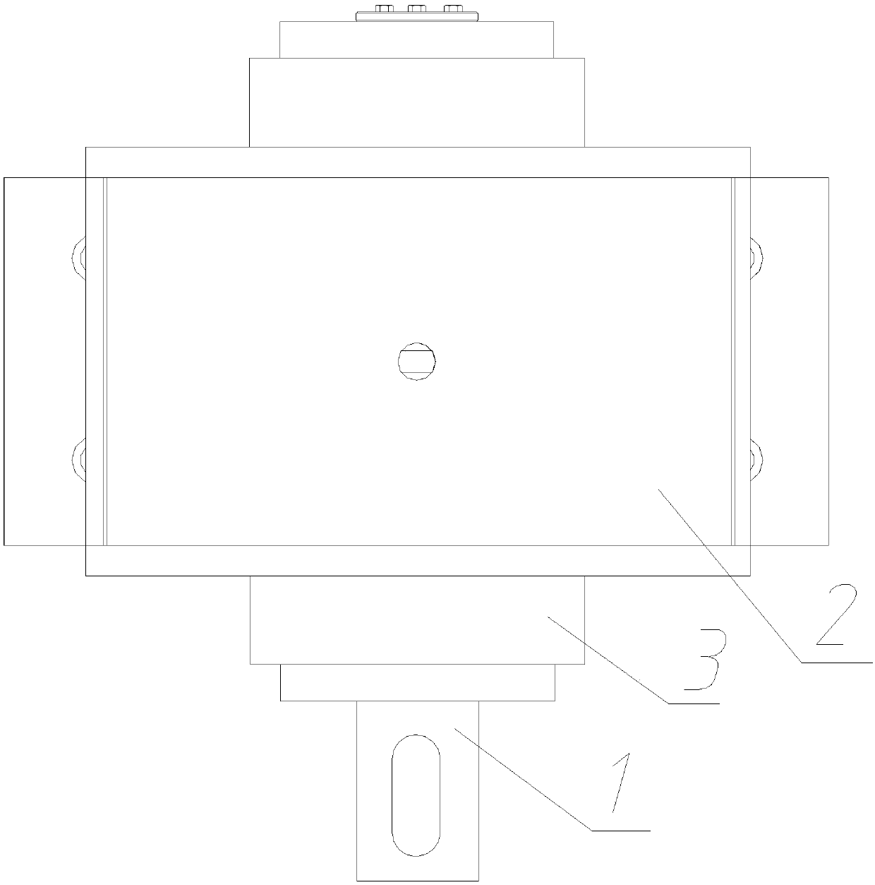
[0033] see Figure 1~3 , in an embodiment of the present invention, a permanent magnet synchronous motor for a guide bar-salient pole hybrid elevator includes a machine base 2, which is internally arranged on a stator core 5, and both ends of the machine base 2 are provided with The end cover 3 and the stator core 5 are provided with a rotor core 6, and the side of the rotor core 6 is provided with a mounting groove, and a permanent magnet 9 is provided in the...


PUM


Abstract

The invention discloses a permanent magnet synchronous motor for a guide bar-salient pole hybrid elevator. The motor comprises a machine base, an internal part of the machine base is provided with a stator iron core, both ends of machine base are provided with end covers, an internal part of the stator iron core is provided with a rotor iron core, a side face of rotor iron core is provided with amounting groove, and a permanent magnet body is arranged in the mounting groove; in the permanent magnet synchronous motor for the guide bar-salient pole hybrid elevator disclosed in the invention, aworking method of cutting a rotating magnetic field via use of a mouse cage structure guide bar is adopted, a problem that the elevator cannot be started is solved, and a surface type structure whichis slotted and pasted is adopted to ensure that heat dissipation is realized while a problem of the permanent magnet body falling off can be greatly alleviated; the tile-shaped permanent magnet body is adopted to reduce processing difficulty, lower cost, reduce installation requirements and give full play to the performance of the permanent magnet body. The use of a circular groove ensures a suitable flux barrier, groove processing techniques are simple, and a magnetic flux leakage coefficient is also prevented from being excessively large.

Description

technical field [0001] The invention relates to the technical field of permanent magnet motors, and in particular provides a permanent magnet synchronous motor for elevators of a guide bar-salient pole hybrid type. Background technique [0002] Since the 20th century, my country's social productivity has greatly increased, but natural resources have gradually decreased, and high energy-consuming equipment appears outdated at this time. The data shows that one-half of my country's total power consumption is concentrated in the motor. Compared with the asynchronous motor with high energy consumption and traditional reduction mechanism, people are more and more focusing on the high power factor, small size, Permanent magnet synchronous motor with light weight and other advantages. [0003] The motor is an essential part of the elevator. The evolution and improvement of the elevator motor can reflect the development of the entire motor field to a certain extent. In the late 198...

Claims


Application Information

Patent Timeline
IPC IPC(8): H02K21/46H02K21/14H02K1/27H02K5/04
CPCH02K1/278H02K5/04H02K21/14H02K21/46
Inventor 程峰张周昊陈子康张宗进吉卫喜
Owner JIANGNAN UNIV
Why Eureka
Eureka Blog
Learn More