
Occluders and Closure Devices

An occluder and proximal technology, applied in medical science, surgery, etc., can solve the problems of insufficient contraction force of the occlusion unit, memory metal fatigue failure, low elasticity of polymer materials, etc., and achieve simplified preparation process and locking operation, The effect of not easy to fail and easy to control the size

Active Publication Date: 2020-07-17
LIFETECH SCIENTIFIC (SHENZHEN) CO LTD
View PDF14 Cites 0 Cited by
  • Summary
  • Abstract
  • Description
  • Claims
  • Application Information

AI Technical Summary

Problems solved by technology

However, memory metals or polymer materials are currently used to prepare plugging units. Memory metals may fail due to fatigue during use, and polymer materials are characterized by low or no elasticity, which will lead to a gap between the two plugging units. Insufficient contraction force can not tightly adhere to the two sides of the defect and affect the occlusion effect. Therefore, the occluder needs an effective restraint structure to keep the distance between the two occluder units (that is, the waist height of the occluder) stable, so as to Ensure plugging reliability

Method used


Image

  • Occluders and Closure Devices
  • Occluders and Closure Devices
  • Occluders and Closure Devices

Examples


Embodiment 1

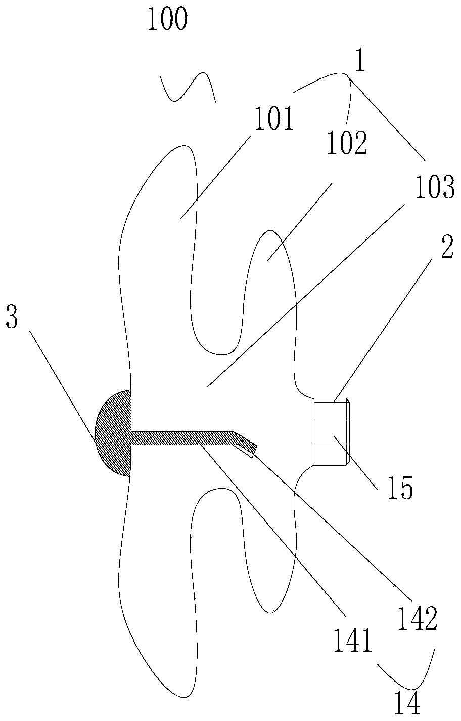
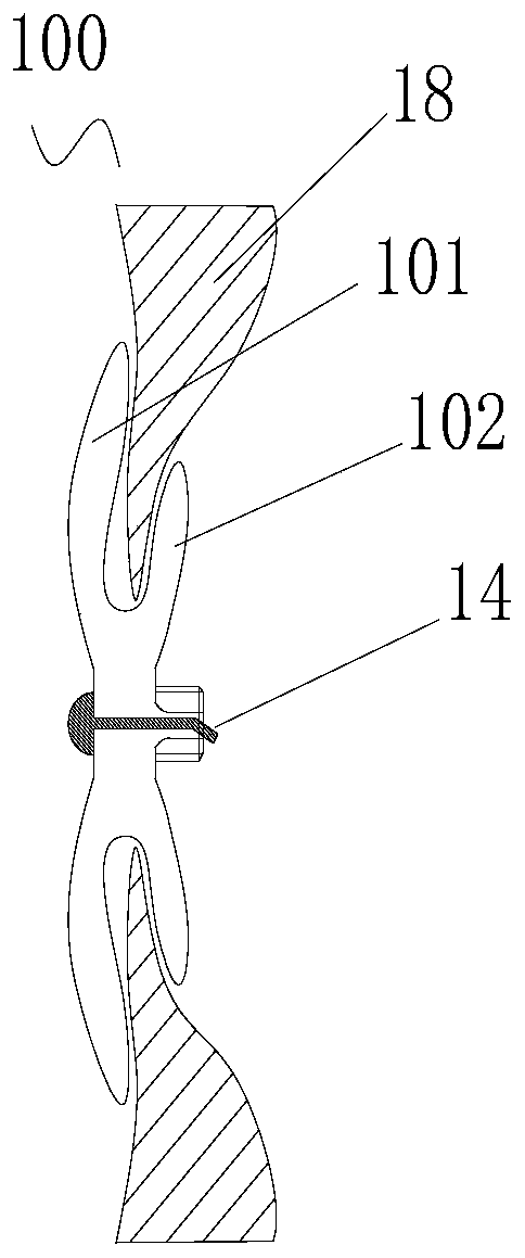
[0041] see figure 1 , the occluder 100 includes a reticular occluder body 1 with a cavity 103, a proximal plug head 2 and a distal end cap 3, the proximal plug head 2 is fixedly connected to the proximal end of the occluder body 1, and the distal end cap 3 is fixedly connected to the distal end of the blocking body 1 . The blocking body 1 includes two disk-shaped first blocking units 101 and second blocking units 102, and the two blocking units 101 and 102 are connected to form an "I" shape. The occluder 100 also includes a locking member 14 located in the cavity 103 . The distal end of the locking member 14 is connected with the distal end of the blocking body 1 . The proximal plug head 2 has a locking hole 15 that communicates with the cavity 103 . Preferably, the locking hole 15 is arranged coaxially with the proximal bolt head 2 .

[0042] It can be understood that the structure of the sealing body 1 is only used as an example, and is not a limitation of the present inve...

Embodiment 2

[0065] see Figure 5 , Another embodiment of the present invention also provides an occluder 100a, the occluder 100a is substantially the same as the occluder 100 provided in the first embodiment, the difference is that in this embodiment, the locking of the occluder 100a The piece 14a includes a connecting portion 141a, a first bending portion 142a and a second bending portion 143a. Wherein, the proximal end of the connecting portion 141a is connected to the distal end of the first bending portion 142a, and the proximal end of the first bending portion 142a is connected to the distal end of the second bending portion 143a.

[0066] Please also refer to Figure 6 There is a first bending angle A1 between the first bending portion 142a and the connecting portion 141a, and a second bending angle A2 between the first bending portion 142a and the second bending portion 143a. Preferably, the first bending angle A1 is the same as the second bending angle A2, the purpose of which i...

Embodiment 3

[0071] Such as Figure 7 As shown, another embodiment of the present invention also provides an occluder 300b. Taking the occluder provided in Embodiment 2 as an example, the occluder 300b in this embodiment includes an occluder 100b, at least a distal opening The hollow conveying mechanism 200b, the lock sleeve 6b used to connect the conveying mechanism 200b and the occluder 100b, and the movable pulling member 4b accommodated in the conveying mechanism 200b. The distal end of the traction member 4b runs through the distal end of the delivery mechanism 200b and can be detachably connected to the proximal end of the locking member 14b in the cavity; the traction member 4b can be pulled under the action of an external force towards the proximal end applied by the operator such as a doctor The locking member 14b drives the distal end of the occluder 100b to move proximally until the proximal end of the locking member 14b passes through the locking hole 15b and presses against th...


PUM


Abstract

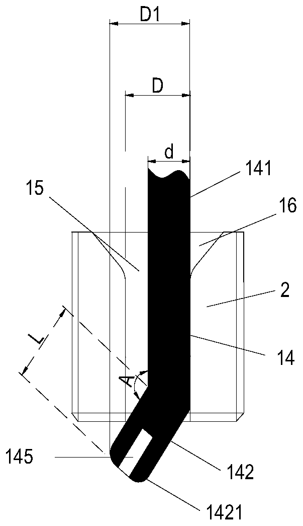
The invention discloses an occluder and a occluder device, which comprise a mesh-shaped occluder body with a cavity and a proximal plug head, the proximal plug head has a locking hole connected with the cavity, and the occluder also includes a locking part, the distal end of the locking part is in contact with the distal end of the blocking body, the locking part is an elastic part, and the locking part includes a connection part connected with the blocking body and a first bending part, which has a first bending angle, and the second The diameter of the circumscribed circle of the projection of a bending portion on a cross section perpendicular to its length direction is smaller than the diameter of the smallest inscribed circle of the locking hole, and the first bending portion is on a plane perpendicular to the longitudinal central axis of the locking hole The projected width of is greater than the diameter of the largest inscribed circle of the locking hole. The invention has the advantages of simple structure, easy control of the size of the locking part, convenient processing, simplified preparation process and locking operation, high locking reliability of the locking part, low failure rate, reversible locking operation process, simple locking process and recovery process.

Description

technical field [0001] The invention relates to an interventional medical device, in particular to an occluder and an occlusion device for interventional treatment of congenital heart disease. Background technique [0002] Percutaneous interventional technology is a disease treatment method that has developed very rapidly in recent years, and the applicable fields of this technology are becoming more and more extensive. Among them, the use of catheter interventional therapy can place various materials, instruments and drugs to the heart, arteriovenous blood vessels of the human body. The device may be a heart defect occluder, a blood vessel plug, a blood vessel filter, and the like. [0003] Transcatheter interventional occluder is a commonly used device in transcatheter interventional therapy, which can be used for minimally invasive treatment of congenital heart diseases such as atrial septal defect, ventricular septal defect, patent ductus arteriosus and patent foramen o...

Claims


Application Information

Patent Timeline
Patent Type & Authority Patents(China)
IPC IPC(8): A61B17/00
CPCA61B17/0057A61B2017/00606A61B2017/00623A61B2017/00619A61B2017/00867
Inventor 陈贤淼
Owner LIFETECH SCIENTIFIC (SHENZHEN) CO LTD
Learn More