Novel modular pure electric cargo van chassis

A modularized, logistics vehicle technology, applied in vehicle components, electric power units, substructures, etc., can solve the problems of weak carrying capacity and driving stability, easy damage to batteries under direct force, and long power transmission paths. The effect of high stability, low cost and good mechanical structure

Pending Publication Date: 2018-10-23
浙江众帮新能源科技有限公司
View PDF1 Cites 1 Cited by
  • Summary
  • Abstract
  • Description
  • Claims
  • Application Information

AI Technical Summary

Problems solved by technology

[0002] At present, most of the domestic new energy logistics vehicles are modified by adding batteries and motors to the existing internal combustion engine models. The power output by the motor on the front side is transmitted to the reducer of the rear axle of the vehicle through the rotating shaft. The power transmission path is long, the power loss is large, and the mass of the vehicle is relatively large.
At the same time, because of the existence of the transmission shaft running through the front and rear, the batteries in the prior art are generally arranged on both sides of the frame. Although this arrangement is convenient for battery replacement, it has the disadvantage that the battery is easily damaged when it is subjected to a lateral impact. , and further easily lead to the problem of fire ie pollution
At the same time, this arrangement makes the width of the frame smaller, and its carrying capacity and driving stability are weaker.
[0003] As described in the Chinese invention patent with the publication number CN107878175A, the chassis of a pure electric logistics vehicle has battery packs arranged on both sides of the frame. Although it is convenient to replace, the battery is easily damaged and further dangerous due to lateral impact. risks of
At the same time, it is a structure with front motor and rear drive, its power transmission path is long, and it takes up a lot of chassis volume

Method used


Image

  • Novel modular pure electric cargo van chassis
  • Novel modular pure electric cargo van chassis
  • Novel modular pure electric cargo van chassis

Examples


Embodiment Construction

[0036] The present invention is described in detail below in conjunction with accompanying drawing:

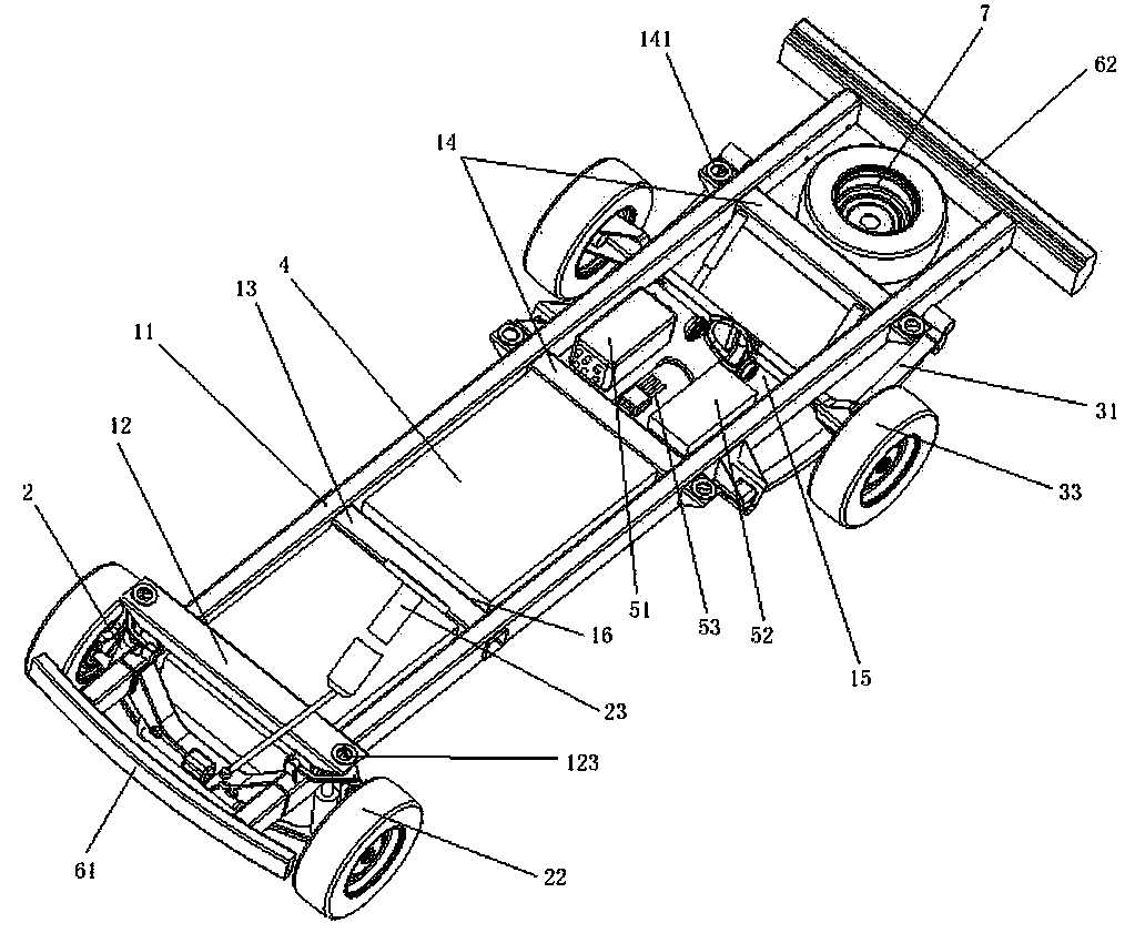
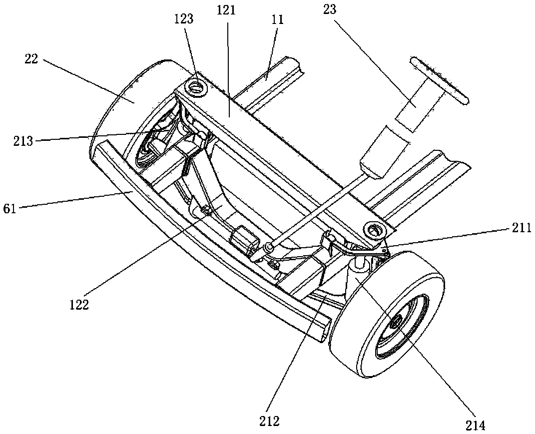
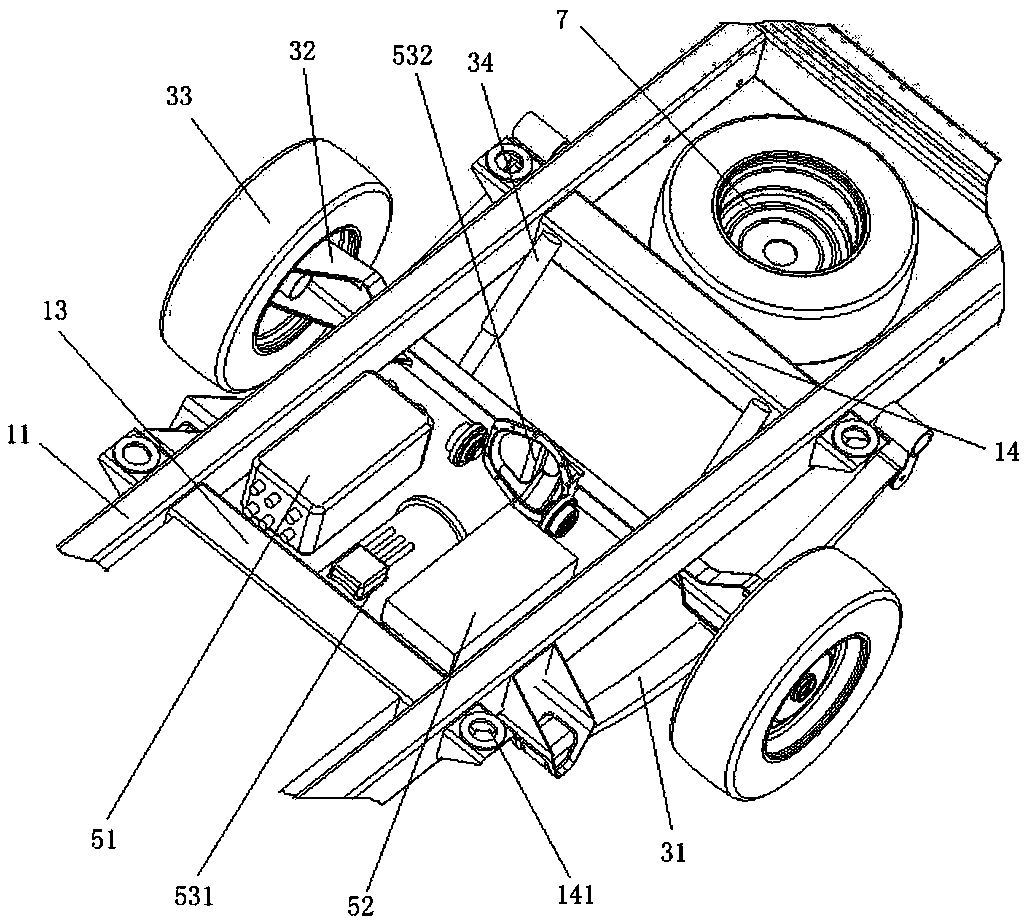
[0037] like figure 1The chassis of a new type of modular pure electric logistics vehicle shown includes the following components: a chassis frame, which includes two straight beams 11 arranged in parallel, a front beam 12 arranged in sequence from front to back, two middle beams 13 and two A rear crossbeam 14, two rear crossbeams 14 and the straight beam 11 form a drive cavity 15, and two cavities 16 are formed between the middle crossbeam 13 and the front and rear crossbeams 14. The front walking assembly, the front walking assembly includes independent suspensions 21 symmetrically arranged on both sides of the front beam 12, front drive shafts passing through the independent suspensions 21, front wheels 22 arranged at both ends of the front drive shafts and connecting independent suspensions 21. Steering assembly 23; rear travel assembly, the rear travel assembly includes l...


PUM


Abstract

A novel modular pure electric cargo van chassis comprises the following components of a chassis frame, a front traveling assembly, a rear traveling assembly, a battery component and a control drivingcomponent. The chassis frame comprises two straight beams which are parallelly arranged, front cross beams which are sequentially arranged from front to back, one or more middle cross beams and two rear cross beams. The two rear cross beams and the straight beams form a driving cavity, and the middle cross beams form a cavity together with the front cross beams and the rear cross beams. The fronttraveling assembly comprises independent suspension symmetrically arranged on the two sides of the front cross beams, front driving shafts arranged on the independent suspension in a penetrating mode,front wheels arranged at the two ends of the front driving shafts, and steering components connected with the independent suspension. The rear traveling assembly comprises plate spring suspension symmetrically arranged on the two sides of the driving cavity, and a rear driving component fixedly connected to the plate spring suspension. The battery component is detachably arranged in the cavity. The control driving component comprises a power distribution component, a control component and a motor assembly which are arranged in the driving cavity and sequentially connected. The novel modular pure electric cargo van chassis has the advantages of being simple in structure, high in strength, good in safety and stability and high in comfort.

Description

technical field [0001] The invention relates to the technical field of new energy logistics vehicle equipment, in particular to a novel modular pure electric logistics vehicle chassis. Background technique [0002] At present, most of the domestic new energy logistics vehicles are modified by adding batteries and motors to the existing internal combustion engine models. The power output by the motor on the front side is transmitted to the reducer of the rear axle of the vehicle through the rotating shaft. The power transmission path is long, the power loss is large, and the mass of the vehicle is relatively large. At the same time, because of the existence of the transmission shaft running through the front and rear, the batteries in the prior art are generally arranged on both sides of the frame. Although this arrangement is convenient for battery replacement, it has the disadvantage that the battery is easily damaged when it is subjected to a lateral impact. , and further...

Claims


Application Information

Patent Timeline
Patent Type & Authority Applications(China)
IPC IPC(8): B62D21/02B60K1/04
CPCB62D21/02B60K1/04B60K2001/0438
Inventor 孙立明周必水苏菲菲
Owner 浙江众帮新能源科技有限公司
Why Eureka
Try Eureka