Double-wing-plate strong support pressure-reducing gate valve

A double-wing plate and gate valve technology, which is applied in the direction of sliding valves, valve details, valve devices, etc., can solve the problems that the ball cannot be accurately aligned with the valve seat, failure, spring performance degradation, etc., and achieve the effect of convenient daily maintenance

Inactive Publication Date: 2018-10-23
CHANGSHA UNIVERSITY OF SCIENCE AND TECHNOLOGY
View PDF5 Cites 0 Cited by
  • Summary
  • Abstract
  • Description
  • Claims
  • Application Information

AI Technical Summary

Problems solved by technology

[0004] 1. In the hydraulic execution circuit of the prior art, the main drive oil circuit is the main path through which the hydraulic fluid passes, and various abnormal conditions are prone to occur. When abnormal conditions occur, such as overpressure conditions, the pipeline ruptures or other faults
[0005] 2. The gate valves in the prior art often only have a cut-off function, and the single function cannot adapt to various complex working conditions
[0006] 3. Due to the dynamic sealing of the check valve in the prior art, such as the cooperation of the spring, the ball and the valve seat, it is difficult to achieve good sealing
And after a long time of use, the performance of the spring decreases, and the ball cannot be accurately aligned with the valve seat.
[0007] 4. The size of the gate valve in the prior art cannot be adjusted in real time when it is specifically adapted to the working environment, especially for the driving parts. When the size of the cut-off body cannot be adjusted, the adjustment of the size of the driving parts is often particularly important
[0008] 5. The adjustment scheme of the valve stem in the prior art is often flexible enough, but not strong enough to be used for a long time under heavy load
[0009] 6. Due to the long-term use of the driving source, more maintenance is required, and there is a lack of maintenance means in the prior art

Method used


Image

  • Double-wing-plate strong support pressure-reducing gate valve
  • Double-wing-plate strong support pressure-reducing gate valve
  • Double-wing-plate strong support pressure-reducing gate valve

Examples


Embodiment Construction

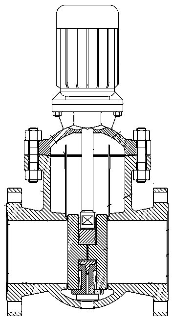
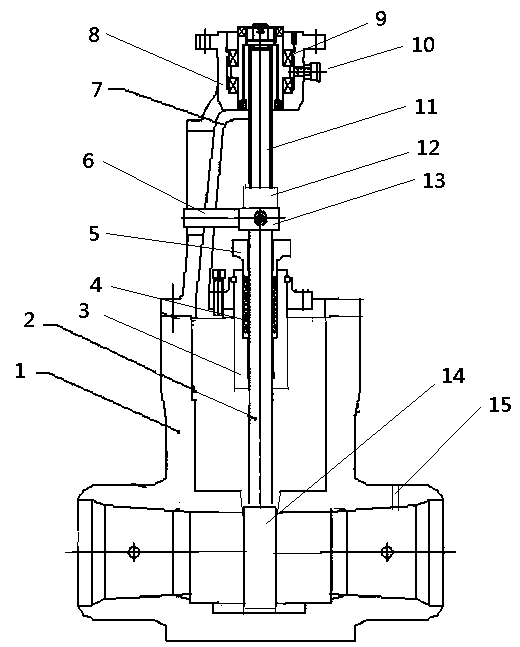
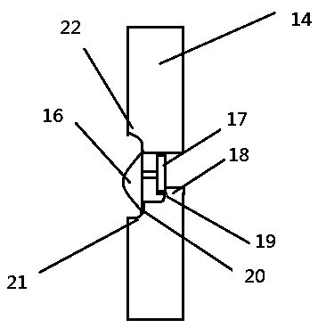
[0034] As shown in the figure: a double-wing plate strongly supported pressure reducing gate valve, the pressure reducing gate valve includes a valve body, a lower valve stem, a stuffing box, packing, a packing gland, a valve stem support frame, a bracket, a flange, a bearing, a lubricating Nozzle, upper valve stem, support ring, support seat, gate, sampling hole, umbrella wing, plate wing, first step, first arc, second step, second arc, third arc; above the valve body There is a bracket, the valve body and the bracket are connected by bolts, there is a flange on the top of the bracket, a stem support frame in the middle of the bracket, a support seat at the end of the valve stem support frame, a support ring above the support seat, and two upper and lower sides of the support ring. The upper and lower valve stems are respectively sleeved on the upper and lower valve stems, and the upper valve stem and the lower valve stem are threaded, and the relative positions of the upper a...


PUM


Abstract

A double-wing-plate strong support pressure-reducing gate valve comprises a valve body, a lower valve rod, a stuffing box, stuffing, a stuffing gland, a valve rod supporting frame, a bracket, a flange, a bearing, a lubricating oil nozzle, an upper valve rod, a supporting ring, a supporting seat, a gate plate, a sampling hole, a parasol wing, a plate wing, a first step, a first arc part, a second step, a second arc part and a third arc part. A through hole is formed in the gate plate and internally provided with a pressure reducing valve. The pressure reducing valve has the following structuresthat the pressure reducing valve is arranged in the through hole and comprises the parasol wing located on the downstream side and the plate wing located on the upstream side, the parasol wing and the plate wing are connected through a rod, the diameter of the parasol wing is larger than the diameter of the plate wing, the upper end of the parasol wing is flush with the upper end of the plate wing and is in pivot connection with the gate plate, and the upper end of the plate wing is in sealed connection with the gate plate.

Description

technical field [0001] The invention relates to the related fields of fluid control, in particular to a pressure-relief gate valve strongly supported by double-wing plates. Background technique [0002] The hydraulic cylinder execution system is a commonly used execution system, which controls the reciprocating motion of the hydraulic cylinder through the main hydraulic drive circuit and the hydraulic drive branch circuit for driving. Gate valve is one of the common components. [0003] In actual use, the existing execution system and gate valve have the following problems: [0004] 1. In the hydraulic execution circuit of the prior art, the main drive oil circuit is the main path through which the hydraulic fluid passes, and various abnormal conditions are prone to occur. When abnormal conditions occur, such as overpressure conditions, the pipeline ruptures or other failures. [0005] 2. The gate valves in the prior art often only have a cut-off function, and the single ...

Claims


Application Information

Patent Timeline
Patent Type & Authority Applications(China)
IPC IPC(8): F16K3/02F16K3/314F16K3/36F16K47/04F15B13/02
Inventor 李方义王鑫曾超茂严宇飞
Owner CHANGSHA UNIVERSITY OF SCIENCE AND TECHNOLOGY
Why Eureka
Try Eureka