

Water cooling tower with demisting equipment
A technology of defogging equipment and cooling water tower, applied in the field of energy saving and environmental protection, can solve the problems of surrounding environmental pollution, reduce water temperature, waste of water resources, etc., and achieve the effect of reducing pollution, avoiding waste, and realizing recycling and processing.
Inactive Publication Date: 2018-10-23
CHINA PETROLEUM & CHEM CORP +1
View PDF7 Cites 0 Cited by
- Summary
- Abstract
- Description
- Claims
- Application Information
AI Technical Summary
Problems solved by technology
The working principle of the cooling tower is to use the wind blowing in from the lower part of the cooling tower to form convection with the water sprayed from top to bottom. Part of the water evaporates in the convection and takes away the corresponding latent heat of evaporation, thereby reducing the temperature of the water and convection. The heated gas is discharged into the atmosphere under the action of the fan on the top of the cooling tower, and the cooled liquid is recycled, but the disadvantage is that in the process of convective contact heat exchange, a large amount of water is evaporated and consumed, and smaller liquid droplets Entrained by the airflow, causing serious waste of water resources and pollution of the surrounding environment
However, since the pressure drop of the conventional cyclone separator is often as high as 1000Pa~1500Pa, the gas must be pressurized to realize the gas-liquid separation of the cyclone separator, which is complicated and uneconomical
[0004] CN203396259U discloses a water-saving cooling tower, in which nozzles and exhaust fans are installed, the nozzles are connected to bypass valves and air coolers through pipelines, the other end of the air coolers is connected to circulating water pumps, and the other end of circulating water pumps is connected to circulating pools through pipelines , the other end of the bypass valve is connected to the circulating water pool through the pipeline, and the temperature of the hot circulating water entering the cooling tower can be reduced by setting the air cooler, thereby reducing the evaporation loss, but the system is more complicated and the cost is higher
Method used
View moreImage
Smart ImageViewing Examples

Examples
Embodiment 1
[0064] After the cooling tower with demisting equipment of the present invention is used, the white smoke at the gas outlet is obviously eliminated, and the apparent water concentration at the gas outlet is lower than 0.55g / Nm 3 , while the apparent water concentration at the gas outlet of an ordinary cooling tower is 10-15g / Nm 3 , Demist efficiency ≥ 96%.
Login to View More PUM
 Abstract
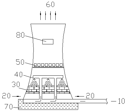
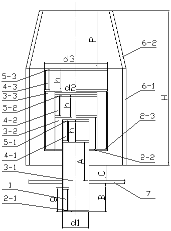
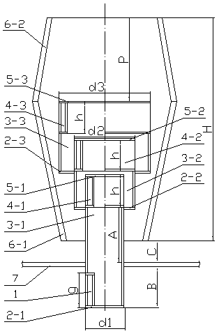
The invention discloses a water cooling tower with demisting equipment. The water cooling tower comprises a cold water tank, a heat dissipation filler, a water distributing system, multi-stage demisting equipment and a fan which are sequentially arranged from top to bottom, wherein an air inlet is formed in the upper portion of the cold water tank; the water distributing system is connected with ahot water pipeline; and a gas outlet is formed in the top of the water cooling tower. The multi-stage demisting equipment comprises a plurality of demisting assemblies which are arranged in parallel,wherein each demisting assembly comprises a multi-stage gas lifting tube and an outer barrel, the multi-stage gas lifting tube comprises a plurality of coaxial gas lifting tubes, tube diameters of which are gradually increased stage by step, and the multi-stage gas lifting tube at least comprises two stages, and the tube diameter of the gas lifting tube at each stage is gradually increased. According to the water cooling tower disclosed by the invention, multi-stage demisting equipment is arranged for gathering a great number of liquid-state frog drops which are taken away by gas flow in a convection contact and heat exchange process, so that severe waste of water resources is avoided, pollution on surrounding environment is reduced, the structure is simple, pressure drop is small, mounting is convenient, and recycling for discharged water mists of the water cooling tower can be effectively realized.
Description
technical field [0001] The invention relates to a cooling tower with demisting equipment, which belongs to the technical field of energy saving and environmental protection. Background technique [0002] Cooling towers are buildings used to cool water, and are generally widely used in factories such as power plants, chemical plants, and cement plants that require a large amount of water temperature control. The working principle of the cooling tower is to use the wind blowing in from the lower part of the cooling tower to form convection with the water sprayed from top to bottom. Part of the water evaporates in the convection and takes away the corresponding latent heat of evaporation, thereby reducing the temperature of the water and convection. The heated gas is discharged into the atmosphere under the action of the fan on the top of the cooling tower, and the cooled liquid is recycled, but the disadvantage is that in the process of convective contact heat exchange, a larg...
Claims
Login to View More Application Information
Patent Timeline
 Patent Type & Authority Applications(China)
IPC IPC(8): F28C1/16F28F25/02B01D45/08
CPCF28C1/16B01D45/08F28F25/02
Inventor 方向晨王晶李欣王海波金平韩天竹李磊
Owner CHINA PETROLEUM & CHEM CORP