
Particle flow parameter measuring device and method based on laser backward scattering method

A backscattering method and flow parameter technology, applied in the direction of analyzing materials, instruments, etc., can solve the problems of optical path deviation, affecting the measurement accuracy, and the large size of the optical probe.

Inactive Publication Date: 2018-10-23
SOUTHEAST UNIV
View PDF4 Cites 2 Cited by
  • Summary
  • Abstract
  • Description
  • Claims
  • Application Information

AI Technical Summary

Problems solved by technology

However, these devices have certain limitations in terms of optical path and hardware design, as well as the selection of optical components.
Mainly reflected in: the optical system is prone to optical path deviation and system drift during long-term use, which seriously affects the measurement accuracy; more lens gratings are used in the optical path design, which increases the cost and reduces the stability of the measurement system The size of the optical probe is large, which has a certain impact on the measurement object and reduces the measurement accuracy; the speed and concentration of the particle flow cannot be measured in an integrated way, and most equipment can only measure the speed or concentration alone

Method used


Image

  • Particle flow parameter measuring device and method based on laser backward scattering method
  • Particle flow parameter measuring device and method based on laser backward scattering method
  • Particle flow parameter measuring device and method based on laser backward scattering method

Examples


Embodiment Construction

[0086] Below in conjunction with accompanying drawing, the present invention is described in detail:

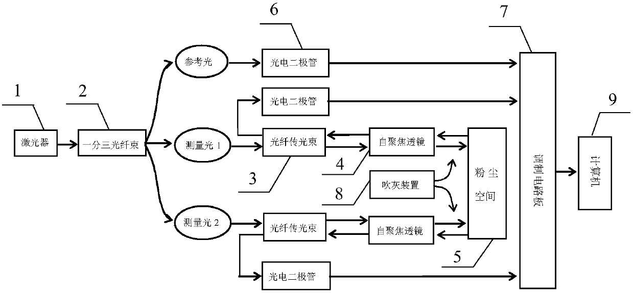
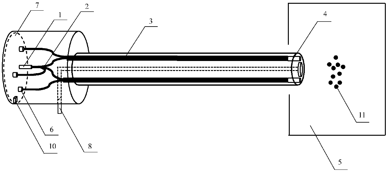
[0087] The present invention is a particle flow parameter measurement device based on laser backscattering method, such as figure 1 , figure 2 shown, including:

[0088] The device used to measure particle flow parameters includes a 635nm semiconductor laser 1, a split-three optical fiber bundle 2, an optical fiber transmission beam 3, a self-focusing lens 4, a dust space 5, a photodiode 6, a modulation circuit board 7, a soot blowing device 8 and a computer 9. Wherein the soot blowing device 8 and the computer 9 are external devices, and other devices are enclosed in a cylinder structure. like figure 2 As shown, the front end is the optical probe; the back end is the chassis, where the system power supply, laser generation, photoelectric conversion, signal acquisition and processing are all completed.

[0089] The probe is the core part of the optical system, such as ...


PUM


Abstract

The invention discloses a particle flow parameter measuring device and method based on a laser backward scattering method. The measuring device comprises an optical fiber probe, which is used to emitlaser on a dust area and collect the scattered light of the dust area; a photoelectric conversion circuit, which converts the optical signals of reference light and scattered light into electric signals; and a computer, which calculates the particle flow parameters of the dust area based on the electric signal obtained by the photoelectric conversion circuit. The probe structure of a monolithic laser optical fiber splitter is utilized; the negative influence of non-synchronous operation of multi-lasers is eliminated, at the same time, one optical path is taken as the reference light, and the measuring precision of the system is improved. The photoelectric conversion and signal processing circuit converts the backward scattered light containing particle flow information into electric signals, and the particle concentration is measured. At the same time, a double channel cross-correlation algorithm is adopted to calculate the flow speed of particles. The speed, concentration, and flow offlowing particles are integrally measured.

Description

technical field [0001] The invention belongs to the technical field of particle flow measurement, and in particular relates to a particle flow parameter measurement device and method based on a laser backscattering method. Background technique [0002] Particle flow systems are widely used in many industrial fields such as energy, chemical industry and metallurgy. Realizing the on-line and accurate measurement of gas-solid two-phase flow is of great significance to improving industrial production efficiency and realizing energy saving and environmental protection. The measurement of particle flow parameters is often accompanied by harsh measurement conditions, such as vibration, high temperature, high pressure, etc. These factors bring great difficulties to the accurate measurement of particle flow parameters and equipment installation. With the development of sensing technology, various sensors are widely used in the measurement of multiphase flow, and the accuracy and sta...

Claims


Application Information

Patent Timeline
Patent Type & Authority Applications(China)
IPC IPC(8): G01N15/00
CPCG01N15/00
Inventor 许传龙奚国强李舒李健张彪
Owner SOUTHEAST UNIV
Learn More