Inductive temperature sensing

An inductive, temperature-sensing technology, used in thermometers, temperature measurement in household appliances, thermometer applications, etc., can solve problems such as sensor operating temperature contamination errors, increased cost and thermal insulation, etc.

Active Publication Date: 2018-10-23
THE TECHNOLOGY PARTNERSHIP PLC
View PDF6 Cites 8 Cited by
  • Summary
  • Abstract
  • Description
  • Claims
  • Application Information

AI Technical Summary

Problems solved by technology

[0003] Infrared temperature sensing is commonly used where non-contact temperature sensing is required, but this suffers from several disadvantages including limited operating temperature of the sensor, accumulation

Method used


Image

  • Inductive temperature sensing
  • Inductive temperature sensing
  • Inductive temperature sensing

Examples


Embodiment Construction

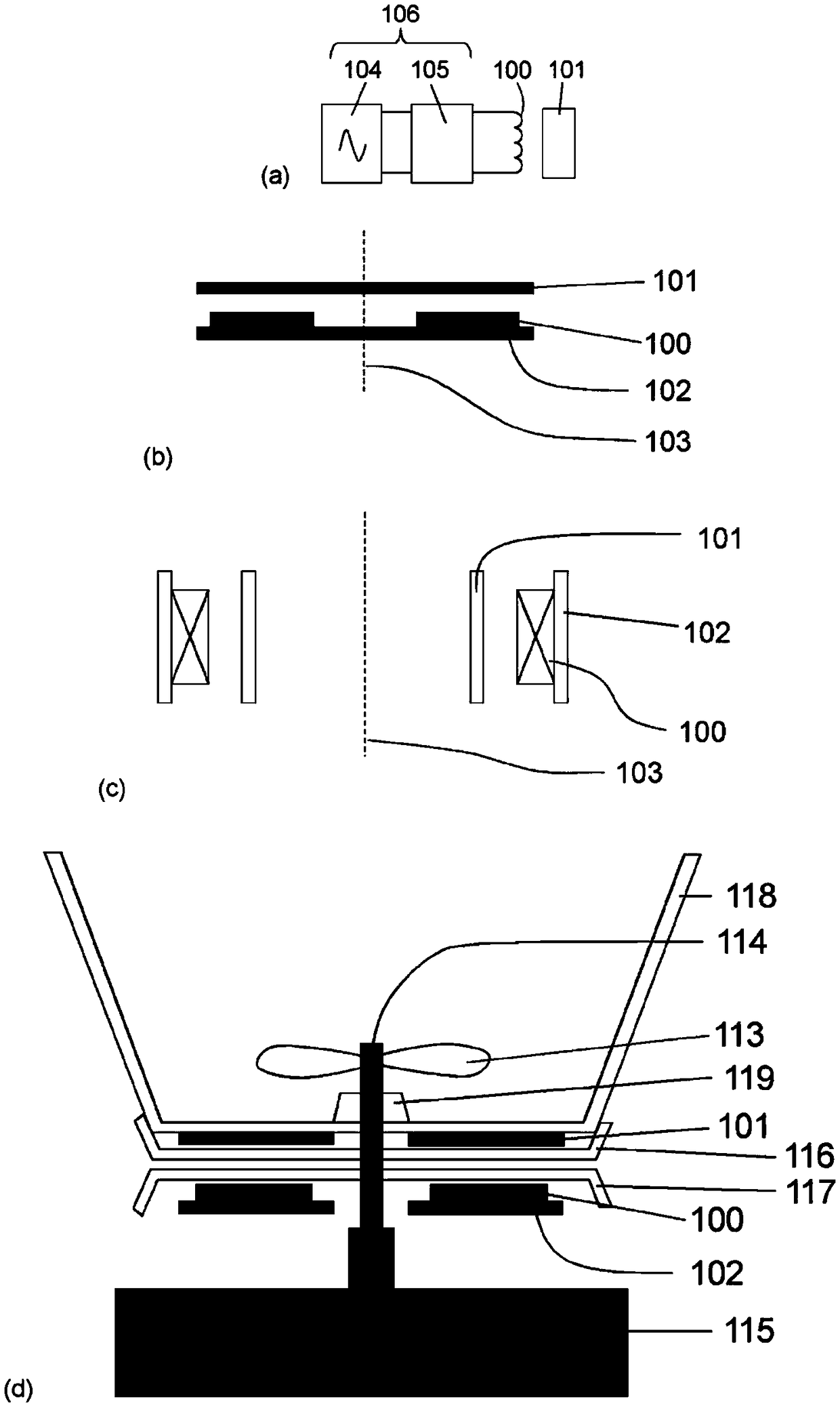
[0030] figure 1 (a) shows the elements of the inductive temperature sensing system. The coil arrangement (100) is energized by an AC signal from an excitation circuit (104). The apparent impedance of the coil construction is measured or inferred by a measurement circuit (105). Note that the excitation and measurement functions may be integrated into a single circuit, such as a microprocessor, and together form the "impedance measurement circuit" (106). The apparent impedance of the coil construction is affected by the nature and temperature of the target (101). Targets that are conductive and magnetically sensitive, ie have a non-zero magnetic susceptibility, are also said to be permeable. The frequency at which the apparent inductance of the coil construction (100) is equal to the inductance of the coil construction (100) in the absence of the target (101) is measured. In this application we call this frequency the cross-over frequency (cross-over frequency). As describe...


PUM


Abstract

An apparatus for inductive temperature sensing comprises a coil configuration, a target, and an impedance measurement circuit. The target has a non-zero conductivity and susceptibility and the impedance measurement circuit measures the apparent inductance of the coil configuration at a measurement frequency close to the crossover frequency to provide an indication of temperature of the target.

Description

technical field [0001] The invention relates to an inductive method of measuring temperature and the use of the inductive method in induction heating applications. Background technique [0002] Many prior art temperature sensing methods of sensors such as thermocouples and resistance temperature detectors (RTDs) require thermal contact between the sensors. This approach is limited at extremely high temperatures or in harsh chemical environments where the sensor may have a limited lifetime. These methods are also difficult to apply to moving or vibrating parts because connecting wires are required to transmit signals to external electronics. The connecting wires also make it difficult to maintain thermal insulation between the part being measured and the external electronics / outside world. High pressures or vacuums are often associated with measurements at high or low temperatures, adding an additional level of complexity to the electrical connections. These factors combin...

Claims


Application Information

Patent Timeline
IPC IPC(8): G01K7/38
CPCG01K2207/06G01K7/38
Inventor 大卫·普利
Owner THE TECHNOLOGY PARTNERSHIP PLC
Why Eureka
Try Eureka