
Compressive sintering flue gas desulfurization and denitrification and flue gas white vapor elimination treatment system and process

A sintering flue gas, desulfurization and denitrification technology, applied in the field of sintering flue gas treatment, can solve problems such as failure to raise flue gas temperature, difficulty in achieving standard emission of flue gas, and difficulty in performing SCR denitrification reaction

Pending Publication Date: 2018-10-26
BEIJING JINGCHENGKELIN ENVIRONMENTAL PROTECTION TECH +1
View PDF6 Cites 16 Cited by
  • Summary
  • Abstract
  • Description
  • Claims
  • Application Information

AI Technical Summary

Problems solved by technology

[0016] However, in the technical solution of this patent, the flue gas of this technology comes out of the desulfurization tower, and the temperature of the flue gas is not raised before entering the SCR reactor. up-to-standard emissions

Method used


Image

  • Compressive sintering flue gas desulfurization and denitrification and flue gas white vapor elimination treatment system and process

Examples


Embodiment 1

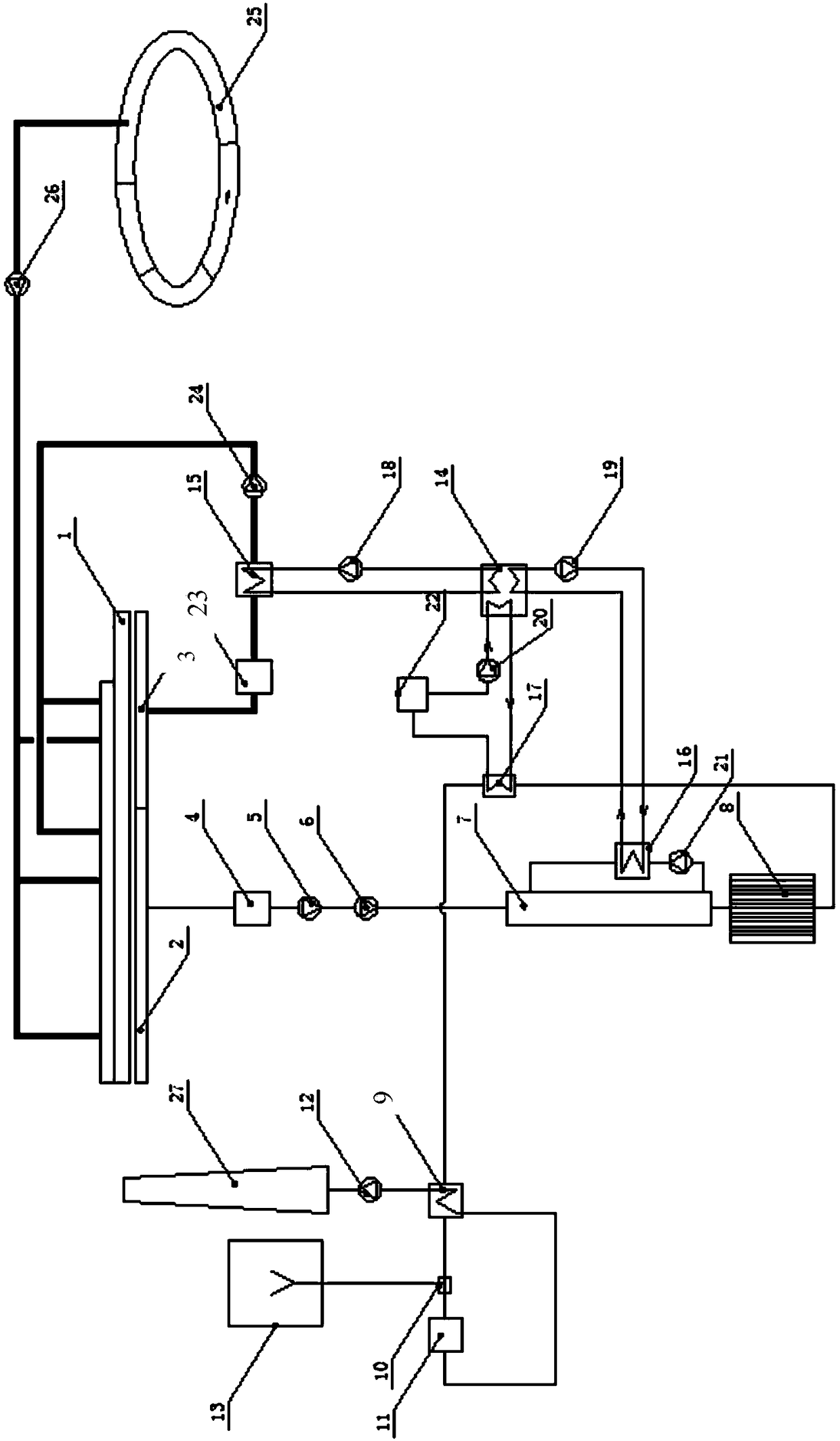
[0073] This embodiment provides a comprehensive treatment system for sintering flue gas desulfurization, denitrification, and flue gas whitening. The structural diagram of the system is as follows figure 1 shown, from figure 1 It can be seen from the figure that the system includes a sintering machine 1, a wet desulfurization tower 7, a denitrification system and a sintering cooler 25, wherein the comprehensive treatment system for sintering flue gas desulfurization, denitrification, and flue gas elimination also includes a second dust collector 23. The convection heat exchanger 15 and the induced draft fan 24. The flue gas outlet of the high-temperature section 3 of the sintering dust fall pipe of the sintering machine 1 passes through the pipeline in sequence through the second dust collector 23, the convective heat exchanger 15, the induced draft fan 24 and the The upper part of the sintering material layer of the sintering machine 1 is connected;

[0074] The comprehensiv...

Embodiment 2

[0086] This embodiment provides a comprehensive treatment process for sintering flue gas desulfurization, denitrification, and flue gas whitening, wherein the process is realized by using the comprehensive treatment system for sintering flue gas desulfurization, denitrification, and flue gas whitening provided in Example 1. Described technique comprises the following specific steps:

[0087] The flue gas produced during the sintering process of the sintering machine enters the dust fall pipe. The flue gas in the falling dust pipe is divided into two parts, one is the sintering low-temperature wet flue gas near the head of the sintering machine, and the other is the high-temperature flue gas near the sintering machine;

[0088] a. The sintering high-temperature flue gas is dedusted in the second dust collector, and then the flue gas obtained after dedusting is subjected to heat exchange in a convection heat exchanger, and the temperature of the sintering high-temperature flue g...


PUM


Abstract

The invention provides a compressive sintering flue gas desulfurization and denitrification and flue gas white vapor elimination treatment system and process. The system comprises a sintering machine,a wet-method desulfurization tower, a denitrification system, a convection current heat exchanger, an air draft blower, a first dust collector, a main exhaust fan, a dehydrator, an absorption type heat pump machine set and a first-stage low-temperature heat exchanger, wherein a low-temperature section flue gas outlet of a sintering dust falling tube of the sintering machine is connected with theflue gas inlet of the desulfurization tower through the first dust collector and the main exhaust fan through a pipeline in sequence; the flue gas outlet of the desulfurization tower is connected withthe denitrification system through the dehydrator; a slurry outlet and a slurry inlet are formed in the wet-method desulfurization tower; the slurry outlet is connected with the slurry inlet througha slurry circulation pump and a cooler in sequence through a slurry circulation pipeline; the absorption type heat pump machine set is arranged between the convection current heat exchanger and the cooler; the first-stage low-temperature heat exchanger is arranged on a pipeline between the dehydrator and the denitrification system; and the first-stage low-temperature heat exchanger is connected with the absorption type heat pump machine set through a pipeline. By adopting the system, flue gas desulfurization and denitrification and flue gas white vapor elimination can be achieved.

Description

technical field [0001] The invention relates to a comprehensive treatment system and process for sintering flue gas desulfurization, denitrification and flue gas whitening, and belongs to the technical field of sintering flue gas treatment. Background technique [0002] In June 2017, the Ministry of Environmental Protection of the People's Republic of China issued a letter on soliciting opinions on 20 national pollutant emission standard revisions (draft for comments) including the "Steel Sintering and Pelletizing Industry Air Pollutant Emission Standards" (Environment Office Atmospheric Letter [2017] 924), which requires that the emission index of nitrogen oxides in the flue gas of the sintering machine head be changed from the existing 300mg / Nm 3 Modified to 100mg / Nm 3 , the sulfur dioxide emission index is changed from the existing 180mg / Nm 3 Modified to 50mg / Nm 3 . [0003] The sintering machine is the largest SO 2 and NOx emission sources. At present, basically all...

Claims


Application Information

Patent Timeline
Patent Type & Authority Applications(China)
IPC IPC(8): B01D53/75B01D53/80B01D53/56B01D53/90B01D53/96B01D53/50B01D53/00F27D17/00
CPCB01D53/002B01D53/343B01D53/50B01D53/75B01D53/80B01D53/8625B01D53/90B01D53/96F27D17/00F27D17/004F27D17/008Y02P10/25
Inventor 杨明华杨源满信保定王治国
Owner BEIJING JINGCHENGKELIN ENVIRONMENTAL PROTECTION TECH
Learn More