Circuit for reducing wireless charging harmonic interference

A harmonic interference and wireless charging technology, which is applied in the direction of circuit devices, high-efficiency power electronic conversion, electrical components, etc., can solve the problem of increasing system complexity and design difficulty, reducing system efficiency, power transmission, and frequency jitter scheme harmonics The attenuation effect is not particularly good, etc., to achieve the effect of reducing wireless charging harmonic interference, simple structure, and low cost

Pending Publication Date: 2018-10-26
浙江泰米电子科技有限公司
View PDF2 Cites 3 Cited by
  • Summary
  • Abstract
  • Description
  • Claims
  • Application Information

AI Technical Summary

Problems solved by technology

[0005] For most of the space shielding schemes, it is mainly aimed at attenuating the magnetic field strength of the near field, because the WPT coil structure is open, and most of the harmonics have high frequencies, so the space shielding scheme is suitable for the far field high frequency Harmonic interference has no effect; and although active coil and reverse current technology have a good attenuation effect on the entire frequency band, it requires an additional set of coils, control, drive and sensing systems, and at the same time Considering the mutual coupling between two sets of coils, this will undoubtedly greatly increase the complexity of the system and the difficulty of design
The frequency dithering scheme and the phase control scheme are specially designed for harmonic attenuation, but the harmonic attenuation effect of the frequency dithering scheme is not particularly good. The degree of attenuation mainly depends on the bandwidth of the frequency modulation, and the bandwidth is too large to reduce the system efficiency. And power transmission; for the phase control scheme, it can only filter the third harmonic and its odd multiple harmonics, and has no attenuation efficiency for the harmonics of the remaining frequencies

Method used


Image

  • Circuit for reducing wireless charging harmonic interference
  • Circuit for reducing wireless charging harmonic interference

Examples


Embodiment Construction

[0017] The present invention is described in further detail below:

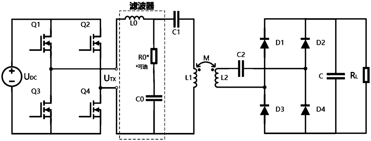
[0018] The invention provides a circuit for reducing harmonic interference of wireless charging, which includes an inverter unit, an inductive coupling unit and a rectifier unit, wherein the function of the inverter unit is to convert DC to AC, and provide AC voltage for the transmitting end of the inductive coupling unit, and for the inverter The control of the variable unit can adopt the existing technology, such as the voltage control scheme defined by the QI protocol mentioned in the background technology, without repeating it, the function of the inductive coupling unit is to perform wireless energy transmission through coil resonance, and the inductive coupling unit includes The LC resonant module at the transmitting end and the LC resonant module at the receiving end, the function of the rectification unit is to convert AC to DC, and provide DC energy for the load. The LC resonant module at the transmit...


PUM


Abstract

The invention provides a circuit for reducing wireless charging harmonic interference, which comprises an inverter unit, an inductive coupling unit and a rectifying unit, wherein the inverting unit isused for changing direct current to alternating current, and providing an alternating voltage for a transmitting end of the inductive coupling unit; and the inductive coupling unit is used for perform wireless energy transmission through coil resonance; the inductive coupling unit comprises a transmitting end LC resonant module and a receiving end LC resonant module; the rectifying unit is used for changing the alternating current to the direct current and providing direct current energy for the load. The circuit for reducing wireless charging harmonic interference is characterized in that the transmitting end LC resonant module is provided with a second-order filter and has the advantages of simple structure and low cost.

Description

technical field [0001] The invention relates to the technical field of wireless charging circuits, in particular to a circuit for reducing harmonic interference of wireless charging. Background technique [0002] In wireless power transfer (WPT), the most widely used in the market is the QI protocol launched by the WPC Alliance. At this stage, the QI protocol is mainly used in consumer electronics products within 50W, and the coupling resonance frequency is defined at 100KHz. At the same time In order to meet different needs, the QI protocol defines a variety of different system schemes and control schemes. The corresponding control schemes mainly include voltage control, frequency control, phase control and duty cycle control. Among them, voltage control and frequency control are two There are two main control schemes, phase control and duty ratio control are two auxiliary control schemes. Different control schemes have different system parameters and performance, and for ...

Claims


Application Information

Patent Timeline
Patent Type & Authority Applications(China)
IPC IPC(8): H02J50/12H02M1/12H02M7/48H02M7/5387
CPCH02J50/12H02M1/126H02M7/48H02M7/5387H02M7/4815Y02B70/10
Inventor 杨利江胡江浩杨成蒙
Owner 浙江泰米电子科技有限公司
Why Eureka
Try Eureka