A twist-extrusion composite strong-plastic forming method and process device

A process device and combined technology, applied in the field of metal plastic processing, can solve the problems of difficult to form high-performance plate/cylinder components, and achieve the effect of avoiding grain growth and large plastic deformation.

Active Publication Date: 2020-12-01
UNIV OF SCI & TECH BEIJING
View PDF10 Cites 0 Cited by
  • Summary
  • Abstract
  • Description
  • Claims
  • Application Information

AI Technical Summary

Problems solved by technology

[0004] The technical problem to be solved in the present invention is to provide a torsion-extrusion composite strong-plastic forming method and process device for processing high-performance plate / tube components in view of the problem that traditional forming processes are difficult to form high-performance plate / tube components

Method used


Image

  • A twist-extrusion composite strong-plastic forming method and process device
  • A twist-extrusion composite strong-plastic forming method and process device
  • A twist-extrusion composite strong-plastic forming method and process device

Examples


example 1

[0030] Example 1: A torsion-extrusion combined strong-plastic forming method and process device for a magnesium alloy cylindrical part are described in detail in conjunction with the accompanying drawings.

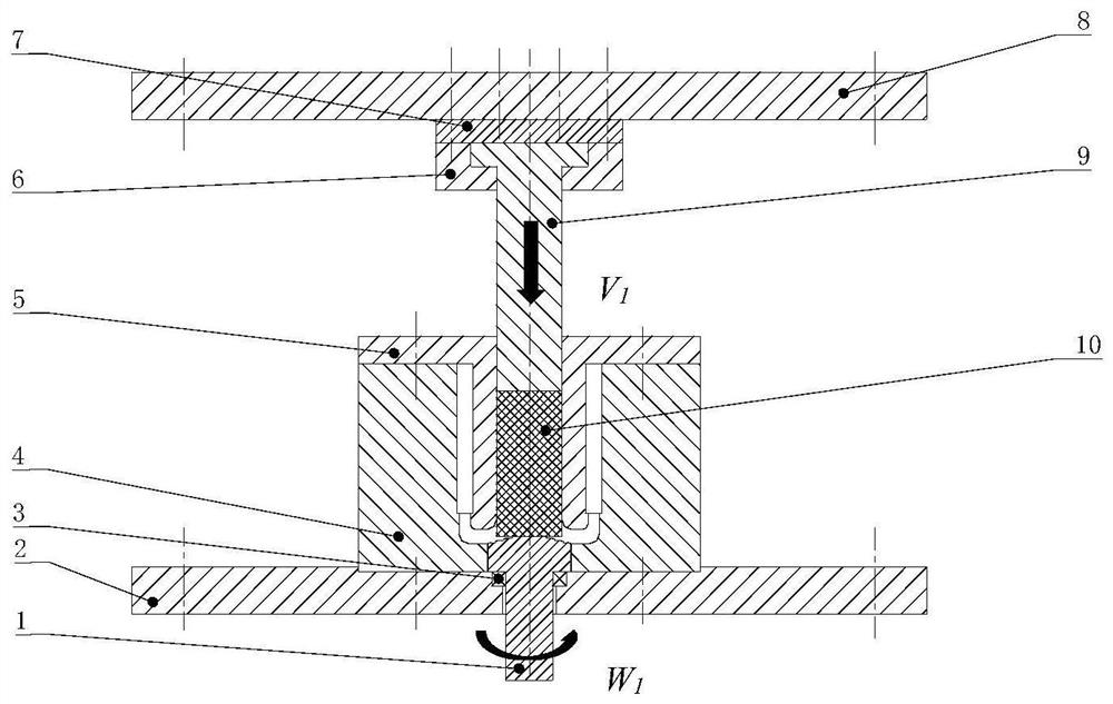
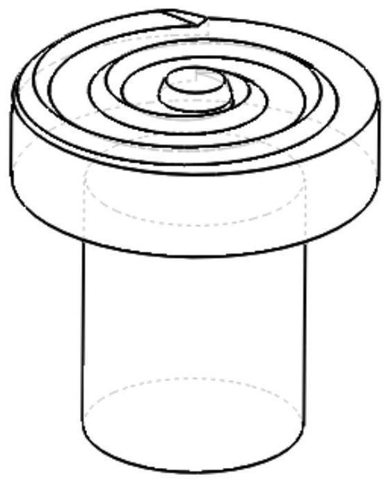
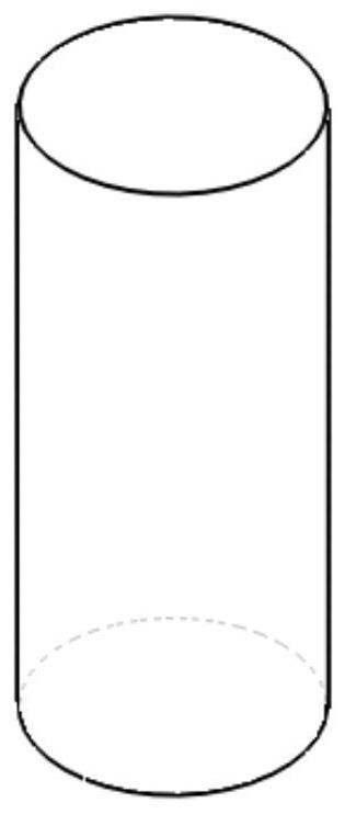
[0031] Such as figure 1 As shown, in the twisting-extrusion combined strong-plastic forming process device for a magnesium alloy cylindrical part, the extruded blank is cylindrical, such as image 3 shown. The steps to use the forming process device are:

[0032] The first step: fix the upper mold seat cover 6, the punch 9 and the backing plate 7 on the upper template 8 by bolts;

[0033] Step 2: Fix the upper template 8 to the slider of the hydraulic press, and fix the lower template 2 to the workbench of the hydraulic press;

[0034] The third step: install the rolling bearing 3 in the groove of the lower template 2;

[0035] Step 4: Fix the lower die 4 on the lower template 2;

[0036] Step 5: Install the rotating head 1 on the rolling bearing 3, and place it in th...

example 2

[0043] Example 2: Combine Figure 6 To illustrate this embodiment, in the twisting-extrusion compound strong-plastic forming process device for magnesium alloy plate-shaped parts, the extruded blank is a square block, such as Figure 7 shown. The combined die of this example is composed of an upper die 5 and a lower die 4; the combined die is fixed on the lower template 2 through the lower mold seat cover 12, and when the blank 10 is extruded, the extrusion speed is V 2 , the rotational speed of the rotating head is W 2 , the metal at the lower end of the billet 10 is subjected to the torsional shearing action of the rotary head 1, and can obtain a fine-grained structure. As the extrusion deformation continues, the metal begins to flow along the concave mold cavity to both sides, forming a plate 13, as Figure 8 shown.

example 3

[0044] Example 3: In the seventh step of this example, the blank 10 is aluminum and its alloys, titanium and its alloys, and a light metal material that is difficult to deform and has better plasticity.

[0045] It should be noted that the specific type of components with complex features depends mainly on the cavity characteristics of the combined die.


PUM


Abstract

The invention provides a torsion-extrusion composite strong-plastic forming method and a technological device, and belongs to the technical field of metal plastic processing. The method combines the advantages of high-pressure torsion fine crystal and extrusion forming, the blank is simultaneously subjected to high-pressure torsion and extrusion, the metal at the lower end of the blank is violently sheared, so that crystal grains are mechanically broken, meanwhile, the temperature rise generated by plastic work and friction power enables the dynamic recrystallization to be refined and the metal plasticity is improved; a large extrusion force is applied to enable the metal to generate plastic flow, and then a high-performance component is obtained through corner deformation in a cavity of aprocess device, and accurate control of property forming and shape forming of the technological process is achieved; and the process device mainly comprises a male mould, a combined female mould, a rolling bearing and a rotary head with a special shape. According to the method and the device, crystal grain refining capacity is strong, the crystal grain growth caused by the heating link of the blank can be avoided by shortening the heating process.

Description

technical field [0001] The invention belongs to the technical field of metal plastic processing, and relates to a torsion-extrusion composite strong plastic forming method and a process device, in particular to a twist-extrusion composite strong plastic forming method for processing high-performance plate / tube components and process equipment. Background technique [0002] With the continuous research and development of advanced aircraft such as large aircraft and large rockets, it is urgent to develop advanced forming methods for complex high-performance components to meet the urgent requirements of overall weight reduction and high reliability. For example, the typical cylindrical parts of spacecraft have harsh environmental conditions and have certain requirements for bearing loads. It is one of the important structures that affect the weight and operational reliability of new models. It is urgent to use high-strength and lightweight alloys to meet the high performance an...

Claims


Application Information

Patent Timeline
Patent Type & Authority Patents(China)
IPC IPC(8): B21C23/00B21C25/02
CPCB21C23/001B21C25/02
Inventor 孙朝阳李广东钱凌云孙志辉苏泽兴蔡贇李昕童
Owner UNIV OF SCI & TECH BEIJING
Why Eureka
Try Eureka