A kind of diamond resin grinding wheel and mold and method for processing the grinding wheel
A resin grinding wheel and diamond technology, applied in the field of grinding and processing, can solve problems such as inconvenience in use and production, and achieve the effects of reducing processing strength, reducing internal space, and increasing structural density
- Summary
- Abstract
- Description
- Claims
- Application Information
AI Technical Summary
Problems solved by technology
Method used
Image
Examples
Embodiment 1
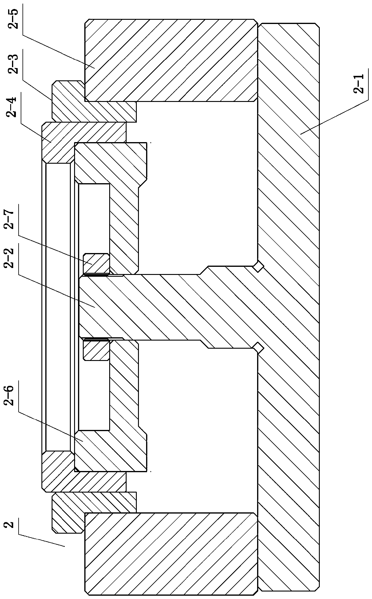
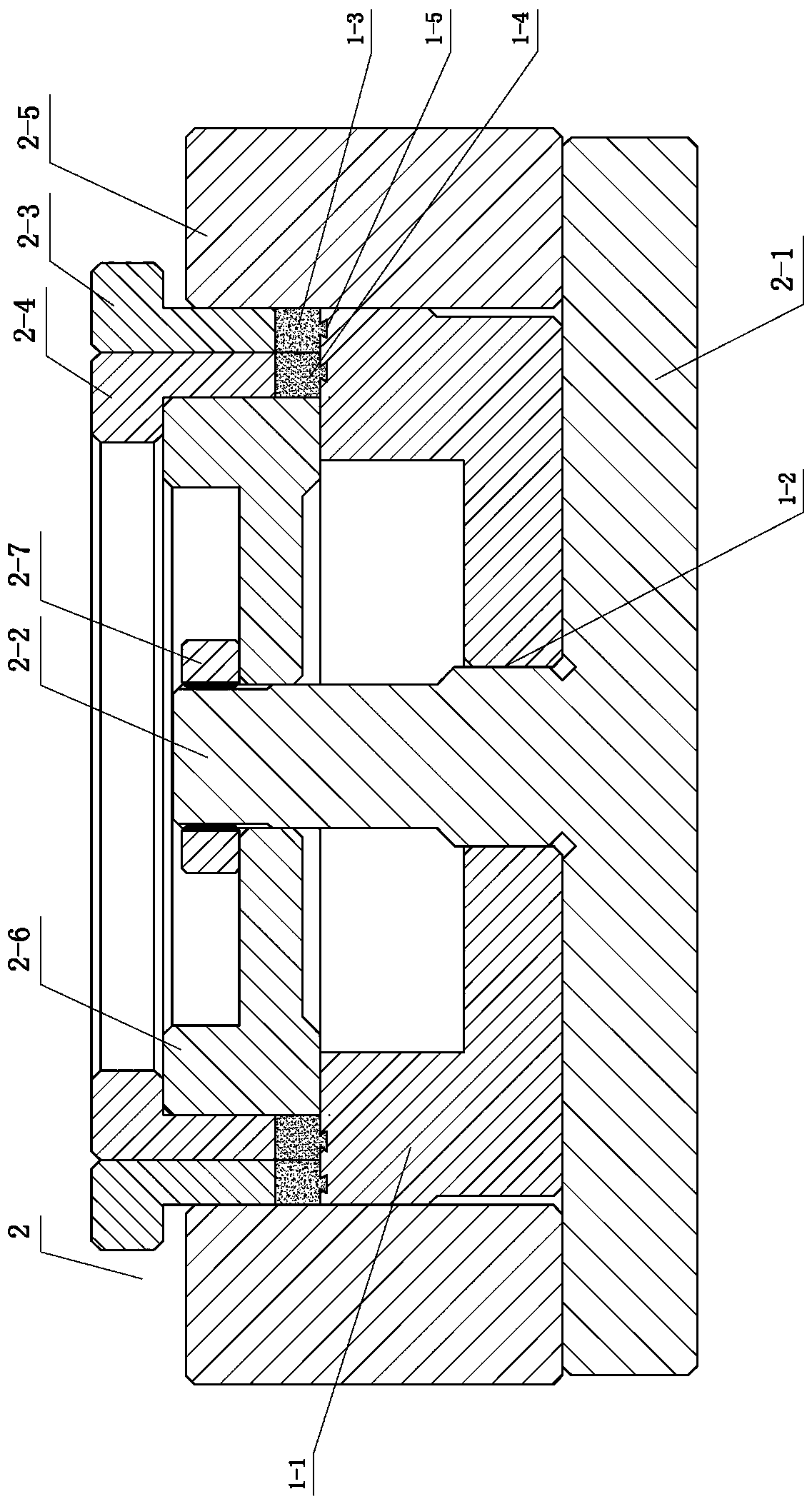
[0042] Such as figure 1 , 2 As shown, the processing mold 2 of the emery wheel of the present invention includes a positioning base 2-1 with a protruding assembly rod 2-2 in the middle, a mold frame 2-5 arranged on the positioning base 2-1, and a mold frame 2-5 sleeved on the assembly rod 2-2. Center die 2-6 on 2. Wherein: the inner wall of the mold frame 2-5 and the bottom surface of the central mold 2-6 form a placement area for the diamond resin grinding wheel substrate 1-1. There is a gap between the inner wall of the mold frame 2-5 and the outer wall of the central mold 2-6, and a coarse abrasive laminating head 2-3 and a fine abrasive laminating head 2-4 are arranged in the gap, and the coarse abrasive laminating head 2-3 is sleeved outside the fine abrasive laminating head 2-4, and can realize the pressing and forming of the coarse-grained abrasive layer 1-3 and the fine-grained abrasive layer 1-4 on the diamond resin grinding wheel substrate 1-1.
[0043] More speci...
Embodiment 2
[0060] Such as Figure 7 As shown, the mould, method and grinding wheel structure used in this embodiment are basically the same as those in Embodiment 1, the main difference is that the fine-grained abrasive layer 4 and the coarse-grained abrasive layer 3 are arranged on the outer circle of the base 1 from the inside to the outside. The fine-grained abrasive layer 4 is bonded to the substrate 1 using a dovetail structure, and the coarse-grained abrasive layer 3 is bonded to the outer circle of the fine-grained abrasive layer 4 . During processing, it is only necessary to move the gap between the coarse abrasive lamination head, the fine abrasive lamination head and the corresponding outer wall of the central mold and the inner wall of the mold frame to the position of the outer circle of the base body 1, first press the inner layer of fine-grained abrasive layer 4, and then Press the outer coarse-grained abrasive layer 3, and the others are all the same as the example 1 metho...
Embodiment 3
[0062] Such as Figure 8 As shown, the present embodiment is basically the same as the embodiment 2, except that the coarse-grained abrasive layer 3 and the fine-grained abrasive layer 4 are superimposed on the outer circle of the substrate 1 . The two abrasive layers are bonded to the substrate 1 respectively using a dovetail structure. During processing, it is only necessary to move the gap between the coarse abrasive laminating head, the fine abrasive laminating head and the corresponding outer wall of the central mold and the inner wall of the mold frame to the outer circle of the base body 1, firstly press the lower fine-grained abrasive layer 4, and then press Upper floor coarse-grained abrasive material layer 3, other are all identical with example 1 method.
PUM
 Abstract
Description
Claims
Application Information
 - R&D
- Intellectual Property
- Life Sciences
- Materials
- Tech Scout
- Unparalleled Data Quality
- Higher Quality Content
- 60% Fewer Hallucinations
Browse by: Latest US Patents, China's latest patents, Technical Efficacy Thesaurus, Application Domain, Technology Topic, Popular Technical Reports.
© 2025 PatSnap. All rights reserved.Legal|Privacy policy|Modern Slavery Act Transparency Statement|Sitemap|About US| Contact US: help@patsnap.com


