Comprehensive test cooling method for vehicle mufflers

A technology of muffler and cooling work, applied in muffler, engine cooling, coolant flow control, etc., can solve the problems of loud noise, accelerated aging of muffler, reduce the volume of two chambers, etc., to reduce noise , the volume increases, the effect of improving the noise reduction effect

Active Publication Date: 2021-01-05
新昌县精锐机械有限公司
View PDF7 Cites 0 Cited by
  • Summary
  • Abstract
  • Description
  • Claims
  • Application Information

AI Technical Summary

Problems solved by technology

The rear muffler on a car has an intake pipe, a cylinder and an exhaust pipe arranged in sequence from front to back. The cylinder of the rear muffler is generally composed of two chambers at the front and rear, and the front end of the cylinder is gradually smaller from the back to the front. Conical surface, the rear end surface of the cylinder is a tapered surface that gradually decreases from front to back, so that the front and rear ends of the cylinder are compressed, reducing the volume of the two chambers, which will affect the noise reduction effect of the muffler
At the same time, the existing muffler does not have a structure that completely eliminates noise for the 80HZ wave frequency band, and the wave frequency band around 80HZ is just the main concentration point of the car's noise, so the car still has a lot of noise after the noise reduction by the muffler
However, the sound in the muffler pipeline cannot be accurately offset and weakened, and the muffler will cause accelerated aging due to overheated exhaust gas, which urgently requires those skilled in the art to solve corresponding technical problems

Method used


Image

  • Comprehensive test cooling method for vehicle mufflers
  • Comprehensive test cooling method for vehicle mufflers
  • Comprehensive test cooling method for vehicle mufflers

Examples


Embodiment Construction

[0033]The present invention will be further described below in conjunction with the drawings and embodiments:

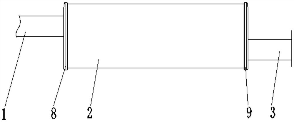
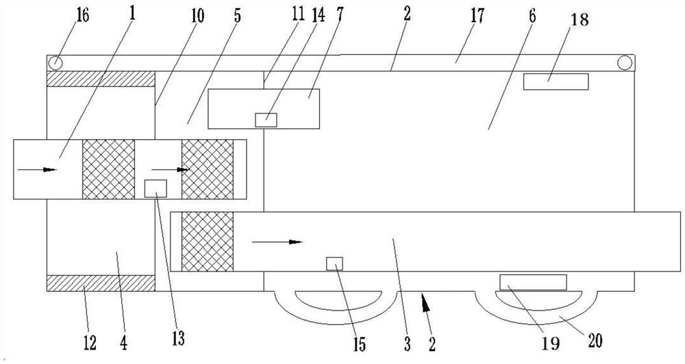
[0034]Such asfigure 1 withfigure 2 As shown, the present invention consists of an intake pipe 1, a cylinder 2, an exhaust pipe 3, a first chamber 4, a second chamber 5, a third chamber 6, a through pipe 7, a front cover 8, a rear cover 9, and a front cover The partition 10 and the rear partition 11 are composed of. Among them, the cylinder 2 is a circular straight cylinder structure. The front end of the cylinder 2 is sealed by the front cover 8 and the rear end is sealed by the back cover 9. Both the front cover 8 and the back cover 9 are preferably circular flat plates, and are welded to the cylinder. Body 2 is fixed. The inside of the cylinder 2 is divided into three chambers by the front partition 10 and the rear partition 11, from the front to the back are the first chamber 4, the second chamber 5 and the third chamber 6, the first chamber 4 The volume of is substantiall...


PUM


Abstract

The invention provides a comprehensive cooling testing working method for vehicle silencing. The method comprises the steps of S1, after tail gas current enters a second chamber through an air inlet pipe, acquiring a sound wave signal of the air inlet pipe by a first standing wave tube; S2, after a single-chip microcomputer receives the sound wave signal of the first standing wave tube, performinganalysis and calculation on the signal of each standing wave tube; S3, mounting a temperature sensor in a silencing device for performing real-time acquisition on an inner air current temperature; S4, sampling the temperature value of a cylinder body by the temperature sensor; S5, determining a voltage floating value through comparing an input voltage change reference signal with a feedback output detecting signal; and S6, if cylinder body temperature reduction cannot be realized because of a fault of a circulating water pump, after the temperature value which is acquired by the temperature sensor exceeds a certain threshold, transmitting a signal to a processor through an overheat protecting circuit, and performing real-time monitoring on operation of the circulating water pipe through acorresponding protecting circuit. The comprehensive cooling testing working method has advantages of ensuring stable operation of a water pump, and prolonging service life of a circulating refrigerating system.

Description

Technical field[0001]The invention relates to a muffler, in particular to a comprehensive test cooling method for vehicle muffler devices.Background technique[0002]Automobile muffler is a common component of automobiles, which is beneficial to reduce noise pollution during automobile driving. The rear muffler on a car has an intake pipe, a cylinder and an exhaust pipe arranged in order from the front to the back. The cylinder of the rear muffler is generally composed of two chambers at the front and the back. The front end of the cylinder is gradually smaller from back to front. Conical surface, the rear end surface of the cylinder body is a tapered surface that gradually becomes smaller from the front to the back, so that the front and back ends of the cylinder body are compressed, reducing the volume of the two chambers, which will affect the noise reduction effect of the muffler. At the same time, the existing muffler does not have a structure for completely silencing the 80HZ wa...

Claims


Application Information

Patent Timeline
Patent Type & Authority Patents(China)
IPC IPC(8): F01N1/06F01N1/02F01P7/16F01P5/12F01P11/00
CPCF01N1/02F01N1/06F01P5/12F01P7/164F01P11/00F01P2050/22
Inventor 陶运群
Owner 新昌县精锐机械有限公司
Why Eureka
Try Eureka