
Electric pressure cooker for quick cooking

An electric pressure cooker and fast technology, applied in the field of kitchen appliances, can solve the problems of complex welding process, power loss, troublesome processing, etc., and achieve the effects of uniform heat transfer, low manufacturing cost and fast heating speed.

Inactive Publication Date: 2018-11-02
ZHAOQING HI TECH ZONE GUOZHUAN TECH CO LTD
View PDF0 Cites 58 Cited by
  • Summary
  • Abstract
  • Description
  • Claims
  • Application Information

AI Technical Summary

Problems solved by technology

[0003] One is to heat the bottom of the pot body through the electric heating plate. The current electric cooker generally uses the heat transfer method of the electric heating plate and the pot body. This method of heating is convenient for processing and assembly, but the thermal efficiency is low. If the surface curvature of the electric heating plate or the inner pot If the curvature of the bottom is deformed, it will cause abnormal heating
[0004] The second is to achieve heating by directly welding or crimping and casting the heating tube at the bottom of the pot body. Although this method can effectively improve the thermal efficiency, the heat generated is concentrated at the electric heating tube, and the heat around the electric heating tube is still uneven. The temperature difference between the hot end and the cold end is large, which may easily lead to burnt phenomenon during cooking
[0005] The third is through the electromagnetic heating method, which can effectively improve the thermal efficiency, and the heat transfer is relatively uniform, but it has high requirements on the material of the pot body, and the cost of the pot body and electric control is also very high, accompanied by the generation of eddy current The coil also generates a lot of heat, and it is necessary to add related heat dissipation equipment to dissipate heat, and at the same time take away part of the electric energy, resulting in a certain amount of electric energy loss
[0006] Fourth, by directly printing the electric heater on the bottom of the pot body or printing the electric heating film on the substrate, and then welding it on the bottom of the pot body, the electric heating film is heated relative to the electric heating tube, and the heat transfer at the bottom is relatively uniform, and there will be no concentrated heat of the electric heating tube However, this connection method has the following disadvantages: electrothermal film printing is divided into insulating layer printing and heating layer printing, so the current product pot body materials basically use ceramics, stainless steel pots and glass-ceramic, but ceramics, stainless steel and micro-glass Crystal glass has the problem of poor heat transfer, which will also affect the cooking effect and cooking time to a certain extent.
Can not reflect the heating advantages of electric heating film
[0007] In addition, the electrothermal film is printed on the substrate and then welded to the bottom of the pot. Due to the printing substrate, the temperature requirement is also high (stainless steel is basically used), and the material requirements for the welding pot body are also high, and stainless steel is basically used. In the prior art, the printing substrate is basically made of stainless steel, and the cost of using stainless steel for the pot body is too high. The difficulty of welding the pot body and the electric heating film is also increased, and the inner surface of the pot body is easy to be damaged after welding. And the surface of the electrothermal film is affected, and the follow-up treatment is more troublesome
[0008] However, from the perspective of cost, electric heating film cookers on the existing market basically use aluminum alloy and other materials with good heat transfer and low cost as the pot material. After the film is welded, it will affect the inner surface of the pot and the surface of the electric heating film. The welding process is complicated and the subsequent surface treatment of the pot body is complicated, which increases the difficulty of the process and the manufacturing cost of the product.

Method used


Image

  • Electric pressure cooker for quick cooking
  • Electric pressure cooker for quick cooking

Examples


Embodiment Construction

[0022] The examples set forth below represent the necessary information to allow those skilled in the art to practice the invention and show the best mode of practicing the invention. Upon reading the following description in light of the accompanying drawing figures, those skilled in the art will understand the concepts of the invention and will recognize applications of these concepts not particularly addressed herein. It is to be understood that these concepts and applications fall within the scope of this disclosure and the appended claims.

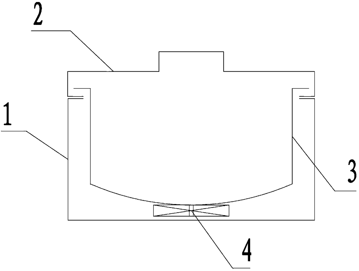
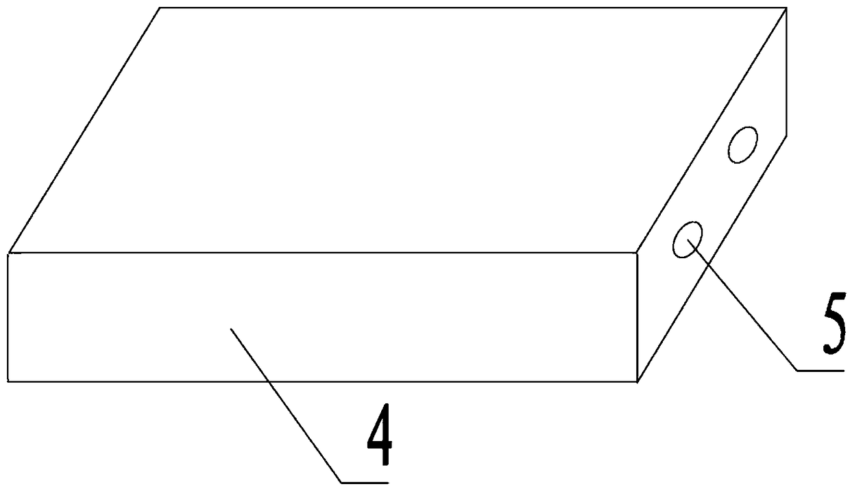
[0023] according to figure 1 It can be known that a fast cooking electric pressure cooker of the present invention comprises a pot body, an upper cover assembly is arranged on the pot body, an inner pot 1 is set inside the pot body, and a main control circuit is arranged in the pot body, so The outer wall of the inner pot 1 is provided with a carbon fiber heating device 2, the carbon fiber heating device 2 is composed of flat bundles...


PUM


Abstract

The invention belongs to the field of kitchen appliances, and relates to an electric pressure cooker, in particular to an electric pressure cooker for quick cooking. The electric pressure cooker comprises a cooker body; an upper cover assembly is arranged on the cooker body; the interior of the cooker body is sleeved with an inner pot; a main control circuit is arranged in the cooker body; the electric pressure cooker is characterized in that a carbon fiber heating device is arranged on the outer wall of the inner pot; the carbon fiber heating device is formed by combining flat bundles of carbon fibers and glass fibers according to a predetermined proportion; an electrical connection terminal is arranged at the end of the carbon fiber heating device; the carbon fiber heating device is fixed on the outer wall of the inner pot by means of a soft insulator; heat-conducting glue or heat-conducting grease is arranged between the carbon fiber heating device and the outer wall of the inner pot; an electric contact convex column matched with the electrical connection terminal is arranged in the cooker body; the electric contact convex column is electrically connected with the main controlcircuit. The electric pressure cooker for quick cooking is simple in structure, easy to connect, rapid in heating speed, uniform in heat transfer and low in manufacturing cost.

Description

technical field [0001] The invention belongs to the field of kitchen appliances, and relates to an electric pressure cooker, in particular to an electric pressure cooker for fast cooking. Background technique [0002] At present, the kitchen electric cooking utensils on the market generally have the following heating methods: [0003] One is to heat the bottom of the pot body through the electric heating plate. The current electric cooker generally uses the heat transfer method of the electric heating plate and the pot body. This method of heating is convenient for processing and assembly, but the thermal efficiency is low. If the surface curvature of the electric heating plate or the inner pot If the curvature of the bottom is deformed, it will cause abnormal heating. [0004] The second is to achieve heating by directly welding or crimping and casting the heating tube at the bottom of the pot body. Although this method can effectively improve the thermal efficiency, the h...

Claims


Application Information

Patent Timeline
IPC IPC(8): A47J27/086
CPCA47J27/086
Inventor 罗志勤
Owner ZHAOQING HI TECH ZONE GUOZHUAN TECH CO LTD
Learn More