A kind of lf furnace dynamic bottom blowing co2-ar refining method and device

A co2-ar, dynamic technology, applied in the field of steelmaking, can solve the problems of easy nitrogen absorption of molten steel, limited Ar blowing strength, and difficulty in rapid deep desulfurization, etc. Effect

Active Publication Date: 2019-04-12
UNIV OF SCI & TECH BEIJING
View PDF3 Cites 0 Cited by
  • Summary
  • Abstract
  • Description
  • Claims
  • Application Information

AI Technical Summary

Problems solved by technology

[0003] In view of the above problems, the present invention proposes a dynamic bottom blowing CO 2 -Ar refining method and device, which solve the technical problems of the existing LF furnace refining process, such as the limited strength of bottom-blown Ar, difficulty in rapid and deep desulfurization, and easy absorption of nitrogen in molten steel

Method used


Image

  • A kind of lf furnace dynamic bottom blowing co2-ar refining method and device
  • A kind of lf furnace dynamic bottom blowing co2-ar refining method and device

Examples


example 1

[0026] Example 1: The present invention is applied to a 90t LF furnace, and the bottom blowing gas is CO 2 Mixed gas with Ar, the initial smelting furnace is a 90t electric arc furnace, the carbon content of the final tapping is 0.10%, 200kg of recarburizer is added during the tapping process, and 100kg of aluminum ingots are added.

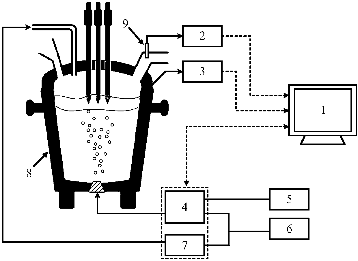
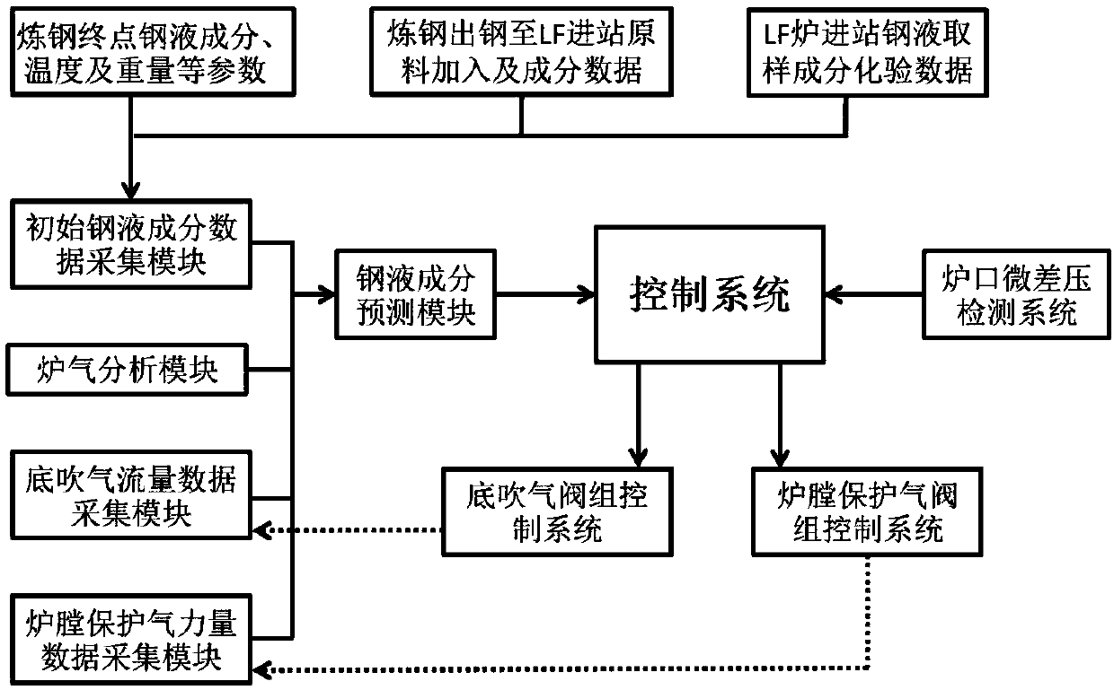
[0027] 1): The molten steel composition data acquisition module obtains the composition data of the electric arc furnace tapping molten steel and the quality and composition data of the smelting materials added to the ladle between tapping and LF furnace entering the station, and calculates the carbon content of the LF furnace refining entering station as 0.45%.

[0028] 2): Preliminary slag removal stage: the control system controls the action of the furnace protection gas control valve group according to the micro pressure difference data at the furnace mouth, and adjusts the furnace protection gas flow rate 0-10Nm online 3 / h, to ensure that ...

example 2

[0036] Example 2: The present invention is applied to a 150t LF furnace, and the bottom blowing gas is CO 2 Mixed gas with Ar, the initial smelting furnace is a 150t converter, and the carbon content of the final tapping is 0.06%. During the tapping process, 300kg of recarburizer, 100kg of aluminum ingot, and 100kg of ferrosilicon are added.

[0037] 1): The molten steel composition data acquisition module obtains the composition data of the electric arc furnace tapping molten steel and the quality and composition data of the smelting materials added to the ladle between tapping and LF furnace entering the station, and calculates the carbon content of the LF furnace refining entering station as 0.35%.

[0038] 2): Preliminary slag removal stage: the control system controls the action of the furnace protection gas control valve group according to the micro pressure difference data at the furnace mouth, and online regulates the furnace protection gas flow rate 0-15Nm 3 / h, to e...


PUM


Abstract

The invention belongs to the technical field of steelmaking, and particularly relates to a LF furnace refining method adopting dynamic bottom blowing for CO2-Ar and applicable to a 30-300t LF furnacerefining process. CO2 and Ar are adopted as a LF furnace bottom blowing medium and hearth protection gas; molten steel components in a refining process are predicted in combination with entering molten steel component data of LF furnace refining and furnace gas component data of the refining process, and on the basis of Ar tracing conservation; the bottom blowing flow rates of CO2 and Ar and the blowing flow rate of the hearth protection gas are dynamically adjusted in different periods of time according to the target molten steel component parameter requirements of the refining; molten pool stirring is carried out in strengthened steel ladle, and a nitrogen content in molten steel is further lowered while rapid deep desulfurization is realized, so that the quality of the molten steel is improved; and meanwhile, CO2 is used for replacing a part of Ar and completing the refining operation, so that the consumption of Ar is reduced, and the production cost is lowered. The LF furnace refining period is shortened by 3-6min, the desulfurization rate achieves 90% above, and the nitrogen content in the molten steel is lowered by 10-30*10<-6>.

Description

technical field [0001] The invention belongs to the technical field of steelmaking, in particular to a dynamic bottom blowing CO 2 -Ar refining method and device. Background technique [0002] LF furnace (Ladle Furnace ladle refining furnace) refining is the main process of converter steelmaking and electric arc furnace steelmaking process. The white slag is desulfurized and smelted, and the bottom blowing Ar is used to stir the molten pool to improve the kinetic conditions of the desulfurization reaction between slag and steel, and to uniform the composition and temperature of the molten pool. And the bottom blowing of Ar is also beneficial to the formation of foamy slag and improves the heat transfer efficiency of the arc. In order to improve the desulfurization of molten steel in traditional LF furnace refining, the method of increasing the Ar flow rate of bottom blowing is generally used to strengthen the bottom blowing stirring and improve the kinetic conditions of mo...

Claims


Application Information

Patent Timeline
Patent Type & Authority Patents(China)
IPC IPC(8): C21C7/064
CPCC21C7/064
Inventor 朱荣魏光升董凯刘润藻武文合韩宝臣吴学涛唐天平姜娟娟彭煜华董建锋田博涵
Owner UNIV OF SCI & TECH BEIJING
Why Eureka
Try Eureka