Turbine front exhaust temperature closed-loop control device and method adopting temperature sensor

A technology of temperature sensor and exhaust gas temperature, which is applied in electrical control, engine control, fuel injection control, etc., can solve the problems of turbocharger maximum boost pressure reduction, engine maximum power influence, large deviation of T3 model, etc., to achieve Increase the engine power, avoid overheating damage to the engine, and improve the effect of engine power

Active Publication Date: 2018-11-02
SAIC MOTOR
View PDF6 Cites 10 Cited by
  • Summary
  • Abstract
  • Description
  • Claims
  • Application Information

AI Technical Summary

Problems solved by technology

The disadvantage of this solution is: the engine T3 is significantly affected by the ambient temperature, and the temperature before the vortex will rise rapidly when the ambient temperature rises
The disadvantage of this solution is: the T3 model deviation in the existing ECU software is relatively large, the general steady-state deviation is ±20°C, and the dynamic deviation is ±30degc
The T3 safety margin of the above two schemes is large, which means that the temperature of the exhaust gas entering the turbine is lower, and the exhaust flow rate will also be reduced, resulting in a decrease in exhaust energy, which will lead to a decrease in the maximum boost pressure of the turbocharger , the maximum power of the engine will be significantly affected

Method used


Image

  • Turbine front exhaust temperature closed-loop control device and method adopting temperature sensor
  • Turbine front exhaust temperature closed-loop control device and method adopting temperature sensor
  • Turbine front exhaust temperature closed-loop control device and method adopting temperature sensor

Examples


Embodiment 1

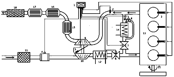
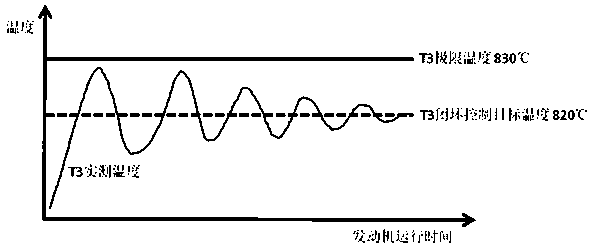
[0052] Please see attached image 3 , the engine 13 can use a certain brand of 2.0T dual-supercharged diesel engine, the power speed is 4000rpm, the limit of the exhaust gas temperature before the vortex is 830°C, and the exhaust temperature before the vortex can be closed-loop controlled within the range of 820°C-830°C.

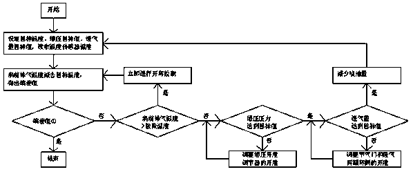
[0053] Set the closed-loop control target temperature of the exhaust gas temperature before the vortex to 820°C, and the engine control unit 1 reads the actual temperature of the exhaust gas temperature before the vortex. If the exhaust temperature before the vortex is =820°C and =830°C and the maintenance time is >3s, immediately perform open-loop control, that is, the fuel injection volume is reduced to the preset value until The exhaust temperature before the vortex is 3s.

[0054] The temperature closed-loop control of T3 is: during the operation of the engine 13, the engine control unit 1 reads the exhaust gas temperature before the vortex detected by t...


PUM


Abstract

The invention discloses a turbine front exhaust temperature closed-loop control device and method adopting a temperature sensor. The temperature sensor (2) is arranged between an oil atomizer (3) anda waste gas turbine (9) and connected with an engine control unit (1). The closed-loop control target temperature value of T3 is set, the engine control unit reads the actual measurement temperature of T3, and if T3 is smaller than the closed-loop control target temperature, control is not conducted; if T3 is larger than or equal to the closed-loop control target temperature and smaller than the extreme temperature, closed-loop control is conducted; if the deviation value is larger than 0, whether the supercharge pressure reaches the target value or not is judged, if the supercharge pressure does not reach the target value, the aperture of a supercharge aperture adjuster (5) is adjusted, and if the supercharge pressure reaches the target value, whether the air inlet volume reaches the target value or not is judged; if the air inlet volume does not reach the target value, the aperture of a waste gas recirculation valve (7) and the aperture of a throttle valve (6) are adjusted; and if T3is larger than or equal to the extreme temperature and the maintaining time is larger than 3 s, open-loop control is immediately conducted, in other words, the oil injection amount is reduced to thepreset value till the T3 is smaller than the closed-loop control target temperature, and the maintaining time is larger than 3 s.

Description

technical field [0001] The invention relates to a control device and method for a diesel engine, in particular to a closed-loop control device and method for exhaust gas temperature before a swirl using a temperature sensor. Background technique [0002] Limited by the temperature resistance limit of materials, the temperature of engine exhaust manifold and turbocharger must be controlled within the limit. Due to the close distance between the two parts, the one with the lower temperature resistance limit of the two parts is selected as the limit value of the exhaust temperature before the vortex (hereinafter referred to as T3) in practical applications, and a certain safety margin is left. If T3 exceeds the limit, it may cause deformation, rupture, air leakage and other failures of the exhaust manifold and turbocharger, damage the engine and cause serious safety hazards. [0003] At present, there are two schemes for T3 control of diesel engine exhaust manifold and superch...

Claims


Application Information

Patent Timeline
Patent Type & Authority Applications(China)
IPC IPC(8): F02D41/14F02D43/00
CPCF02D41/0002F02D41/0007F02D41/1446F02D41/30F02D2041/0022Y02T10/40
Inventor 尚明
Owner SAIC MOTOR
Why Eureka
Try Eureka