
Reciprocating torsion durability test device and test method

A testing device, a durable technology, applied in the direction of measuring device, using repeated force/pulsation force to test the strength of materials, instruments, etc., can solve the problem that product defects cannot be detected, and achieve the elimination of invalid external force interference, stable spindle speed, The effect of simple structure

Pending Publication Date: 2018-11-02
MAANSHAN QILI ELECTRICAL & MECHANICAL EQUIP CO LTD
View PDF1 Cites 5 Cited by
  • Summary
  • Abstract
  • Description
  • Claims
  • Application Information

AI Technical Summary

Problems solved by technology

[0006] Aiming at the lack of equipment for testing disc-shaped or wheel-shaped product cores to withstand torsional force for a long time in the prior art, resulting in the problem that hidden defects of products cannot be detected, the present invention provides a reciprocating torsion durability test device and test method , through the cooperative setting of the tensioning mechanism, pendulum, pulley mechanism, drop device and cam mechanism, etc., the pendulum is driven to swing left and right, and the tensioning mechanism is used as the transmission of the rotating shaft to realize repeated torsional force applied to the core of the workpiece to be measured. The fatigue work effect of the actual working state can effectively monitor and evaluate the reciprocating torsion durability of the workpiece, and the structure is simple and the operation is convenient

Method used


Image

  • Reciprocating torsion durability test device and test method
  • Reciprocating torsion durability test device and test method
  • Reciprocating torsion durability test device and test method

Examples


Embodiment 1

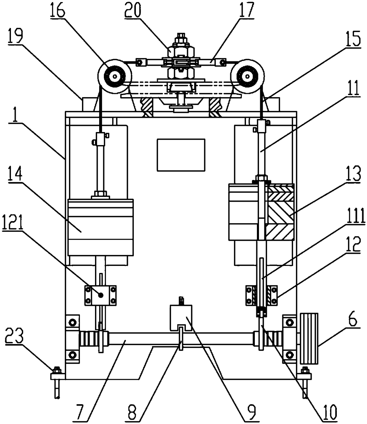
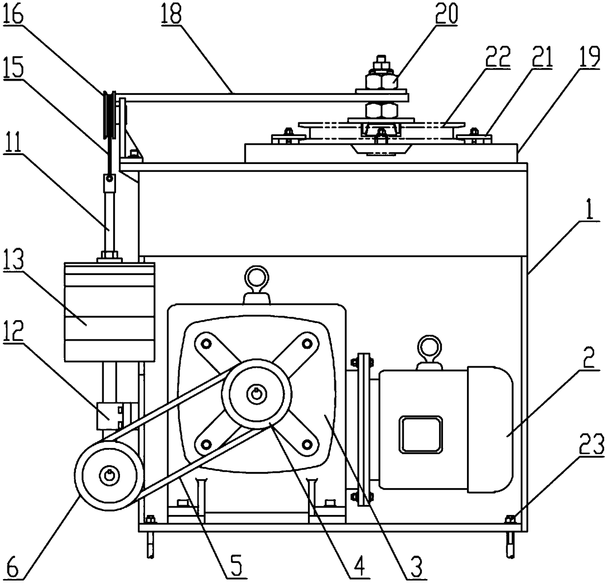
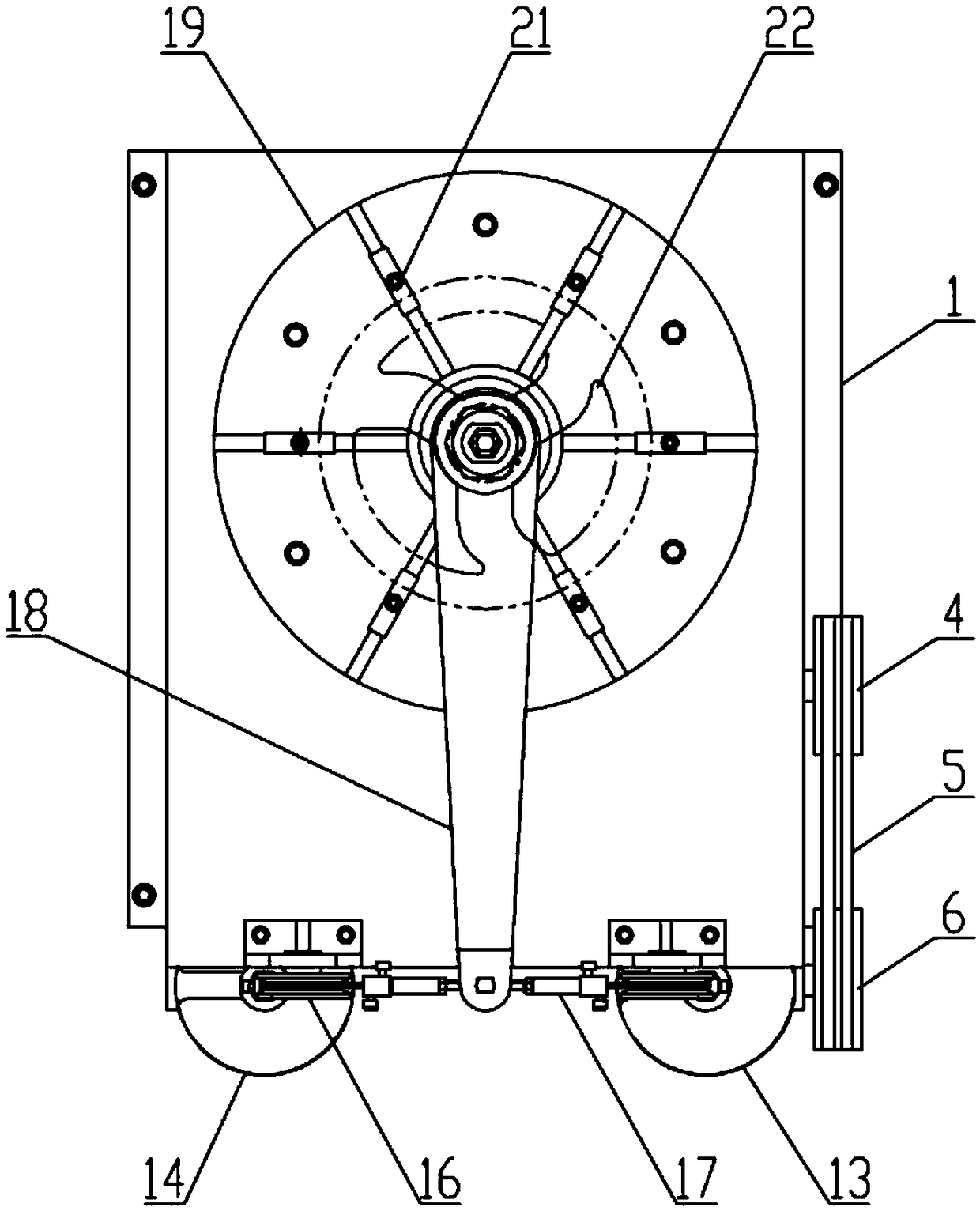
[0052] A reciprocating torsion durability test device, such as figure 1 , 2 , 3, including a box body 1, the box body 1 is fixed on the workbench or the ground by anchor screws 23, and also includes a fixed table 19, a tensioning mechanism 20, a swing rod 18, a pulley mechanism 16, and a falling device , a cam mechanism and a power unit, the fixed table 19 is arranged on the top of the box body 1 for fixing the workpiece 22 to be measured; One end is inserted into the shaft hole of the core of the workpiece 22 to be tested and tightened, and the other end is vertically connected to the swing rod 18; the pulley mechanism 16 is symmetrically arranged on the top of the front side of the box body 1; The upper end of the falling device is connected by a flexible rope 15, and the flexible rope 15 is wound on the pulley mechanism 16, and the falling device falls under gravity to tighten the flexible rope 15; The mechanism 20 is fixedly connected, and the other end is fixedly connec...

Embodiment 2

[0064] A kind of to-and-fro torsional endurance testing device of the present embodiment, the basic structure is the same as that of embodiment 1, the differences and improvements are as follows: figure 1 , 2 As shown, the falling device includes a connecting rod 11, a guide sleeve 12 and a gravity weight, the gravity weight is detachably connected to the connecting rod 11, and the guide sleeve 12 is fixed on the front of the box body 1. side, and slide on the connecting rod 11, so that the connecting rod 11 can slide up and down along the guide sleeve 12; in this embodiment, the gravity weight is sleeved on the connecting rod 11, And fixed by nuts, it is convenient to disassemble and replace the gravity weight, and then adjust the test torque; it can be understood that the gravity weight and the connecting rod 11 can also be connected in other detachable ways.

[0065] Such as figure 1 As shown, the cam mechanism includes a driven wheel 6, a main shaft 7 and two cams 10, th...

Embodiment 3

[0070] A kind of to-and-fro torsion durability testing device of the present embodiment, the basic structure is the same as embodiment 2, the differences and improvements are as follows: figure 2 As shown, the power device includes a motor 2 , a transmission 3 , and a driving wheel 4 that are matched and connected in sequence, and the driving wheel 4 is connected to the driven wheel 6 through a transmission belt 5 . During operation, after the motor 2 is started, the rotating speed is too fast, and after being decelerated by the transmission 3, it is output by the driving wheel 4, and then transmitted to the driven wheel 6 through the transmission belt 5. In this embodiment, the motor 2 is a steplessly variable speed motor with an adjustable speed, thereby being able to adjust the alternating speed of the torsional force, so as to save the detection time to the greatest extent and improve the detection efficiency while meeting the test requirements.

[0071] In the reciprocat...


PUM


Abstract

The invention discloses a reciprocating torsion durability test device and test method, and relates to the field of torsion fatigue testing. The device comprises a box body and also comprises fixed stations, a tensioning mechanism, an oscillating bar, pulley mechanisms, falling devices, cam mechanisms and a power device, wherein the fixed stations are arranged on the top of the box body for fixinga workpiece to be tested; the tensioning mechanism is used as a spindle to be connected with the workpiece to be tested; the pulley mechanisms are symmetrically arranged on the top of the front sideof the box body; the upper ends of the left falling device and the right falling device are connected through a flexible rope; the flexible rope bypasses the pulley mechanisms; one end of the oscillating bar is fixedly connected with the tensioning mechanism, and the other end of the oscillating bar is connected to the middle of the flexible rope; the cam mechanisms are arranged on the front sideof the box body; the lower end of each falling device is in cooperation with the cam mechanisms; the power device is arranged in the box body. According to the reciprocating torsion durability test device, reciprocating torsion force can be applied to the core part of the element to be tested so as to achieve a fatigue work effect on simulating the practical work state of the workpiece, the reciprocating torsion durability performance of the workpiece to be evaluated can be effectively monitored, and in addition, the reciprocating torsion durability test device has the advantages of simple structure and convenience in operation.

Description

technical field [0001] The invention relates to the field of torsional fatigue testing, in particular to a reciprocating torsional durability testing device and a testing method. Background technique [0002] Ferrite is a new type of non-metallic magnetic material that has developed rapidly since the 1940s. Compared with metal magnetic materials, ferrite has the advantages of large resistivity, high dielectric properties, and high magnetic permeability at high frequencies. With the development of science and technology, ferrite is not only widely used in electronic industry sectors such as communication broadcasting, automatic control, computing technology and instrumentation, and has become an indispensable part, but also in space navigation, satellite communication, information display and Pollution treatment and other aspects have also opened up a broad application space. In the production process, ferrite is similar to the general ceramic process, which is easy to oper...

Claims


Application Information

Patent Timeline
IPC IPC(8): G01N3/02G01N3/38
CPCG01N3/02G01N3/38
Inventor 罗晓峰
Owner MAANSHAN QILI ELECTRICAL & MECHANICAL EQUIP CO LTD
Learn More