Network transformer and line hanging method of network transformer

A network transformer and lead wire technology, applied in the field of transformers, can solve the problems of high voltage failure, high production cost and labor cost, and high scrap rate, and achieve the effect of reducing the process of winding lead wires, reducing the risk of short circuit, and the process of hanging wires is simple.

Pending Publication Date: 2018-11-02
MIANYANG HIGHLY TECH JINGWEIDA SCI
View PDF0 Cites 1 Cited by
  • Summary
  • Abstract
  • Description
  • Claims
  • Application Information

AI Technical Summary

Problems solved by technology

This kind of process is complicated, the production process is cumbersome, and the operation is difficult. In the process of winding the wire, it is necessary to control the tightness of the coil lead wire; since the lead wire of the magnetic coil is enameled wire, the part of the tool used for winding the wire that is in contact with the enameled wire needs to be polished Smooth, so that the enameled wire will not be damaged during the winding process. After the enameled wire is damaged, it will cause high voltage failure. If the tool used (for example: tweezers) is too sharp, the lead wire will be broken or broken
In addition, the solder joints of traditional network transformers are large, the amount of tin material is large, the production cost and labor cost are high, and the distance between the two pins of the traditional transformer is narrow after winding, which is easy to cause short circuit and cause high scrap rate The scrap rate of transformers is high, and it is also prone to the risk of hidden dangers in electrical performance

Method used


Image

  • Network transformer and line hanging method of network transformer
  • Network transformer and line hanging method of network transformer
  • Network transformer and line hanging method of network transformer

Examples


Embodiment 1

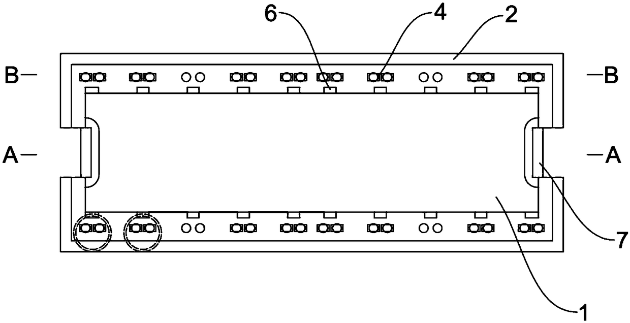
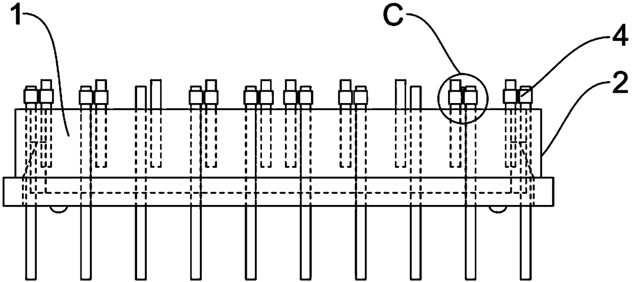
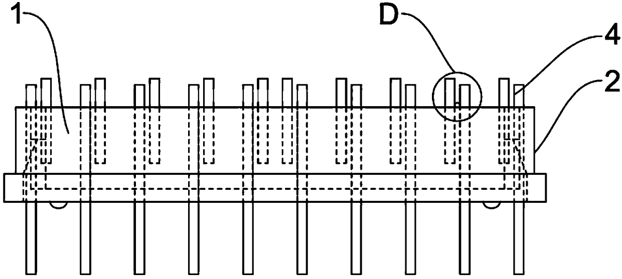
[0043] Embodiment 1: A network transformer, including a housing base 2 with a housing slot 1 for accommodating a magnetic ring coil, a housing upper cover 3 that can be covered on the housing base 2, and a double-row The pin needle 4, the end of the double-row pin needle 4 close to the opening of the accommodating groove 1 is provided with a U-shaped slot 5 for accommodating the lead wire 9 of the magnetic loop coil.

[0044] In this embodiment, the magnetic ring coil is placed in the accommodation slot 1, the lead wire 9 of the magnetic ring coil is fixed in the U-shaped slot 5, and is electrically connected with the double-row pin needle 4, and the upper cover 3 of the housing is closed on the On the housing base 2 , the housing upper cover 3 covers the accommodating groove 1 and one end of the opening of the double-row pin pin 4 located in the accommodating groove 1 , and the housing base 2 is fixed to the housing upper cover 3 . The beneficial effect of this embodiment is ...

Embodiment 2

[0046] Embodiment 2: On the basis of Embodiment 1, the double row of pin needles 4 includes a first pin needle 41 and a second pin needle 42, at one end of the first pin needle 41 close to the opening of the accommodating groove 1 A first boss 411 is provided, and the second pin 42 is provided with a second boss 421 at one end close to the opening of the accommodating groove 1. The shape and structure of the first boss 411 and the second boss 421 are the same, The first boss 411 cooperates with the second boss 421 to form the U-shaped slot 5, the size of the U-shaped slot 5 matches the diameter of the lead wire 9, so that the lead wire 9 is clamped and fixed on the U-shaped card slot 5. Wherein, the first pin needle 41 and the second pin needle 42 are arranged side by side, the end of the first pin needle 41 away from the U-shaped card slot 5 is located outside the housing base 2, and the second pin needle 42 is all located in the housing holder; when in use , the first pin 4...

Embodiment 3

[0048] Embodiment 3: On the basis of Embodiment 1 or 2, a wire passing groove 6 is also provided on the housing base 2, wherein the wire passing groove 6 and the opening of the accommodating groove 1 are located on the housing base 2 On the same side, one end of the wire slot 6 communicates with the opening of the accommodation slot 1, the lead wire 9 of the magnetic ring coil passes through the wire slot 6, and the wire slot 6 clamps the lead wire 9 and fixes the position of the lead wire 9 , the stability of the connection between the lead wire 9 and the U-shaped card slot 5 is enhanced through the wire passage groove 6 provided on the housing deck, and the difficulty of hanging the wire is also reduced. Clamped in the wire slot 6, just snap the movable end of the lead wire 9 into the U-shaped slot 5, because when the lead wire 9 is clamped, the lead wire 9 is first fixed through the wire slot 6 and then snapped into the In the U-shaped card slot 5, the lead wire 9 is in a f...


PUM


Abstract

The invention discloses a network transformer. The network transformer comprises a shell base, a shell upper cover and dual rows of pins, wherein an accommodating groove is formed in the shell base and is used for accommodating a magnetic ring coil, the shell upper cover can cover the shell base, the dual rows of pins are arranged on the shell base, and a U-shaped clamping groove is formed in oneend, near to an opening of the accommodating groove, of each of dual rows of pins and is used for accommodating a lead of the magnetic ring coil. A line hanging method of the network transformer comprises the following steps of (a) placing the magnetic ring coil in the accommodating groove, allowing the lead of the magnetic ring coil to penetrate through a line through groove, and clamping the lead of the magnetic ring coil into the U-shaped clamping groove; (b) welding the lead arranged in the U-shaped clamping groove in the step (a) so that the lead is fixed in the U-shaped clamping groove and electrically communicates with the dual rows of pins; and (c) covering the shell upper cover and fixing the shell upper cover at the shell base.

Description

technical field [0001] The invention belongs to the technical field of transformers, and in particular relates to a network transformer and a wire-hanging method of the network transformer. Background technique [0002] The lead wire of the magnetic coil of the traditional network transformer is connected to the pin needle by winding. There is a gap for winding wire at the terminal of the pin needle. After the wire winding is completed, the coil lead wire is connected to the pin pin of the shell by hand dipping tin to make it electrically conductive. This kind of process is complicated, the production process is cumbersome, and the operation is difficult. In the process of winding the wire, it is necessary to control the tightness of the coil lead wire; since the lead wire of the magnetic coil is enameled wire, the part of the tool used for winding the wire that is in contact with the enameled wire needs to be polished Smooth, so that the enameled wire will not be damaged d...

Claims


Application Information

Patent Timeline
Patent Type & Authority Applications(China)
IPC IPC(8): H01F27/28H01F27/29H01F27/26H01F27/30H01F41/10H01F41/00
CPCH01F27/266H01F27/2828H01F27/29H01F27/306H01F41/00H01F41/10H01F27/027
Inventor 余代春王强
Owner MIANYANG HIGHLY TECH JINGWEIDA SCI
Why Eureka
Try Eureka