Slip ring magnetic coupling mechanism

A magnetic coupling and slip ring technology, applied in transformer/inductor magnetic cores, preventing/reducing unnecessary electric/magnetic influences, inductors, etc., can solve problems such as inconvenient maintenance, easy damage, aging, etc., and achieve use The effect of prolonging life, reducing brush wear, and slowing down external impact

Active Publication Date: 2019-06-18
CHONGQING UNIV +1
View PDF2 Cites 0 Cited by
  • Summary
  • Abstract
  • Description
  • Claims
  • Application Information

AI Technical Summary

Problems solved by technology

[0004] Aiming at the disadvantages of traditional contact rotary energy transmission devices such as easy damage, aging, and inconvenient maintenance during use, the present invention provides a slip ring magnetic coupling mechanism, which selects the sleeve structure and optimizes the magnetic core to realize Wireless energy transfer of energy from the fixed-side part to the rotating-side part of the rotating body with a minimum mass reduction of the coupling mechanism

Method used


Image

  • Slip ring magnetic coupling mechanism
  • Slip ring magnetic coupling mechanism
  • Slip ring magnetic coupling mechanism

Examples


Embodiment Construction

[0028] In order to make the technical problems, technical solutions and advantages to be solved by the present invention clearer, the following will describe in detail with reference to the drawings and specific embodiments. In the drawings, elements or parts are not necessarily drawn in actual scale.

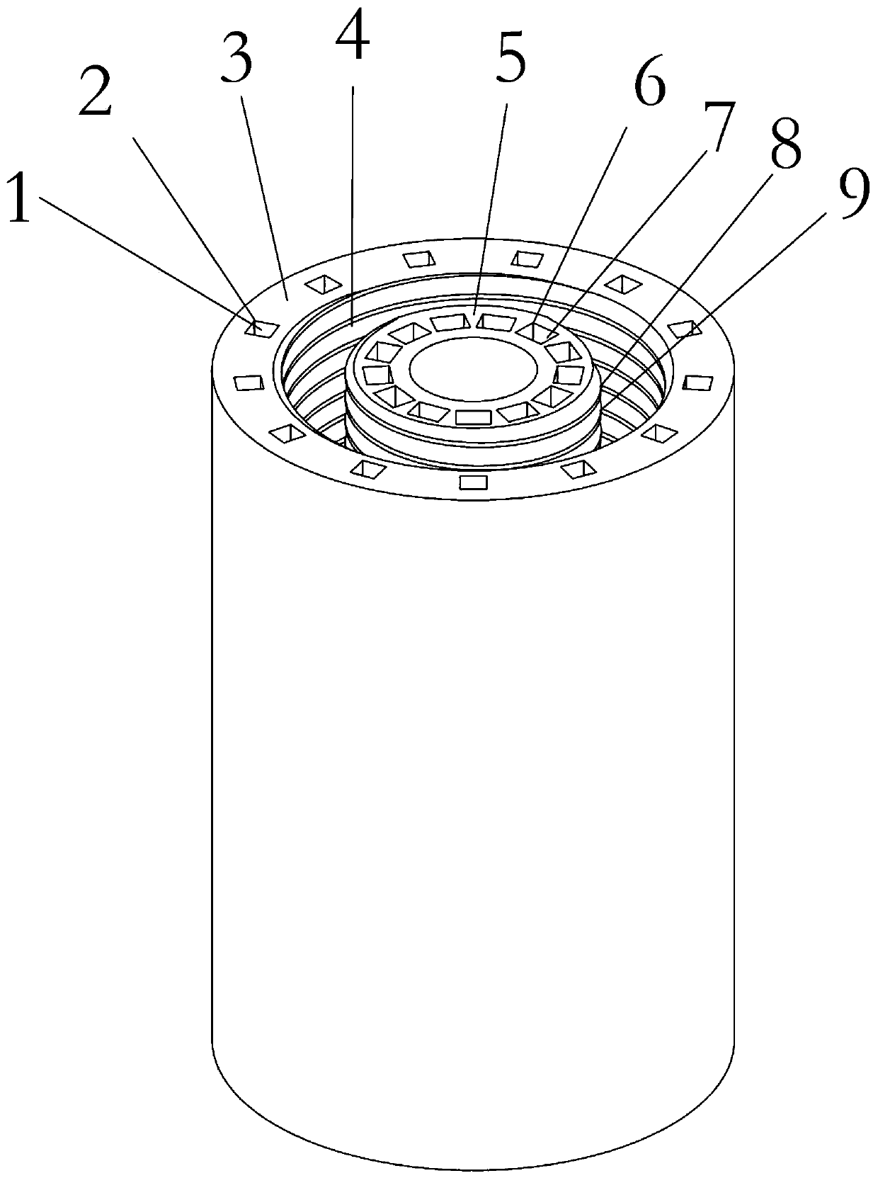
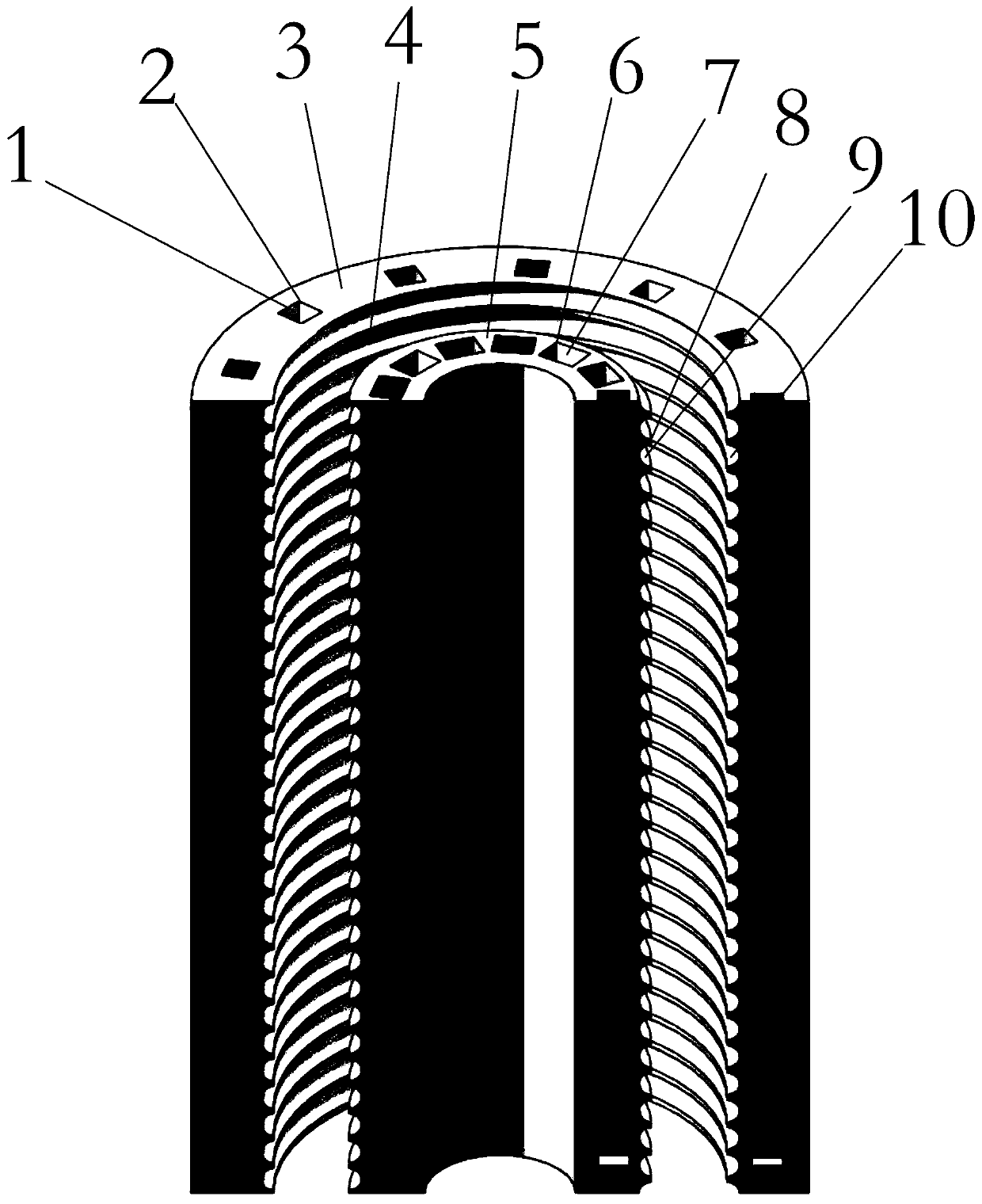
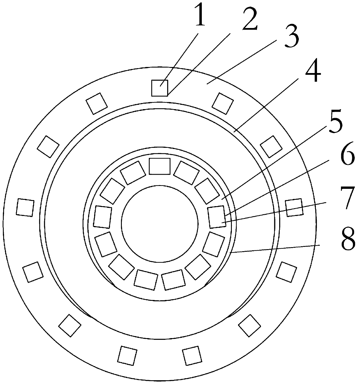
[0029] Such as Figure 1 to Figure 3 As shown, a slip ring coupling mechanism for wireless energy transmission in the present invention includes an outer cylinder coil 4, an outer cylinder magnetic core, an inner cylinder coil 8 and an inner cylinder magnetic core; wherein the outer cylinder coil 4 is tightly wound in a helical column shape Made on the inner surface wall of the outer cylinder magnetic core to form an outer cylinder structure; the inner cylinder coil 8 is tightly wound on the outer surface wall of the inner cylinder magnetic core in a helical column shape to form an inner cylinder structure; the inner cylinder structure and The outer cylinder structure is sheat...


PUM


Abstract

The invention belongs to the technical field of wireless energy transmission, and particularly relates to a magnetic coupling mechanism of a sliding ring. The magnetic coupling mechanism comprises anelectromagnetic coupling mechanism, wherein the electromagnetic coupling mechanism comprise an external cylinder coil, an external cylinder magnetic core, an internal cylinder coil and an internal cylinder magnetic core, and wireless energy transmission can be achieved. By coaxially sleeving an energy emission mechanism and an energy receiving mechanism, the wireless energy transmission of the energy emission mechanism and the energy receiving mechanism can be achieved in a relatively rotation system the groups of magnetic strips are controlled by losing a part of magnetic shielding performance and controlling maximum magnetic induction intensity of the magnetic cores under the condition that the magnetic cores cannot reach magnetic saturation, and the mass of the coupling mechanism is reduced to the greatest extent.

Description

technical field [0001] The invention belongs to the technical field of wireless energy transmission, and in particular relates to a slip ring magnetic coupling mechanism. Background technique [0002] At present, the fixed part and the rotating part of most machines realize the transmission of electric energy through the sliding contact of conductive slip rings, such as solar sail panel drive device (SADA), drone camera, stage lights, etc. when the relevant parts need to rotate Both adopt the contact method of conductive slip ring device to realize energy transmission, but there are certain problems in energy transmission in this way. On the one hand, the slip ring is easily damaged once it is subjected to a large vibration during operation; The life of the ring is easy to decrease. In addition, the interior of the conductive slip ring is generally very complicated, and the process requirements are high, so the cost is high. Therefore, the traditional conductive slip ring ca...

Claims


Application Information

Patent Timeline
Patent Type & Authority Patents(China)
IPC IPC(8): H01F38/14H01F27/24H01F27/26H01F27/28H01F27/30H01F27/36H02J50/10
CPCH01F27/24H01F27/266H01F27/2823H01F27/306H01F27/36H01F38/14H02J50/10
Inventor 叶兆虹王智慧刘秀芳田海林唐春森王海勇朱婉婷
Owner CHONGQING UNIV
Why Eureka
Try Eureka