Circularly polarized orbital angular momentum antenna

An orbital angular momentum and antenna technology, applied in antennas, antenna coupling, antenna components and other directions, can solve problems such as low anti-interference ability, improve anti-interference ability, increase multiple resonance points, improve spectrum resource utilization and The effect of system capacity

Active Publication Date: 2018-11-02
XIDIAN UNIV
View PDF3 Cites 7 Cited by
  • Summary
  • Abstract
  • Description
  • Claims
  • Application Information

AI Technical Summary

Problems solved by technology

The invention realizes the switching between various modes of orbital angular momentum vortex electromagnetic waves by controlling the input phase, but due to the simple structure of the radiation patch, only linearly polarized orbital angular momentum vortex electromagnetic waves can be realized, and the anti-interference ability Low

Method used


Image

  • Circularly polarized orbital angular momentum antenna
  • Circularly polarized orbital angular momentum antenna
  • Circularly polarized orbital angular momentum antenna

Examples


Embodiment 1

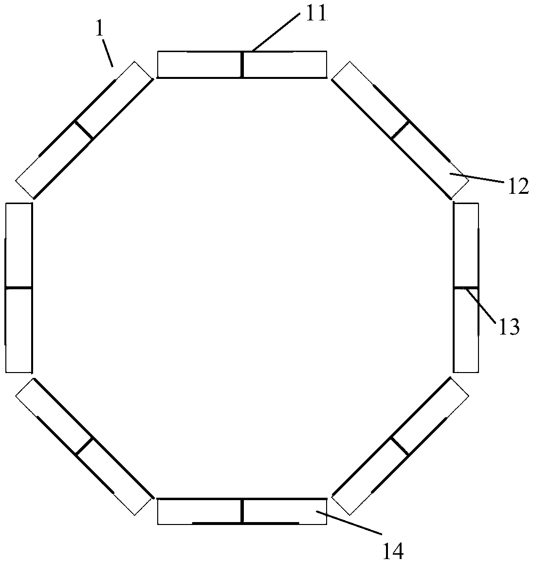
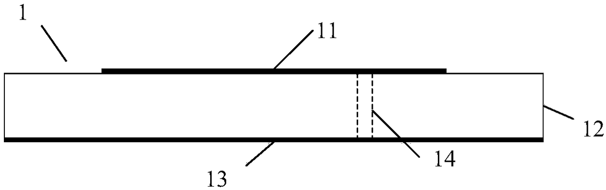
[0023] refer to figure 1 , a circularly polarized orbital angular momentum antenna proposed by the present invention includes eight antenna units 1, the antenna unit 1 includes a dielectric material plate 12, and a radiation patch 11 printed on one side of the dielectric material plate 12 and another The radiant floor 14 on the side, wherein the radiant patch 11 and the radiant floor 14 are connected by a coaxial line 13 . The antenna units 1 are arranged in a hollow columnar structure, and the side of each antenna unit 1 printed with a radiation patch 11 is located outside the hollow columnar structure, forming a conformal array. This structure can effectively suppress the mutual coupling between the units. The characteristics of the antenna unit 1 are maintained, and the performance of the antenna is improved.

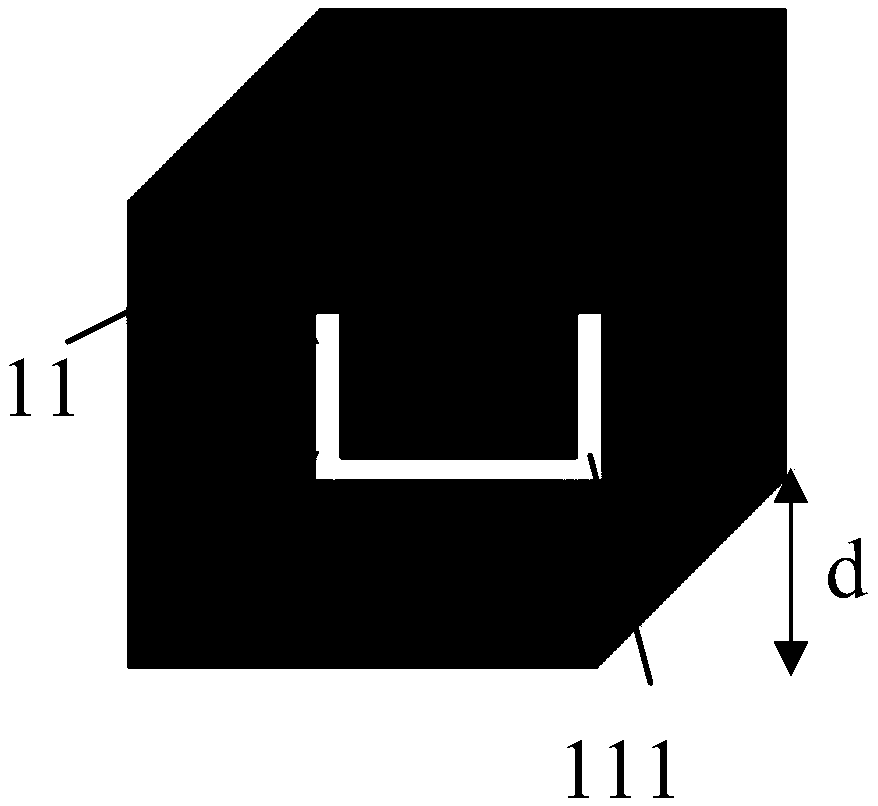
[0024] refer to figure 2 , the geometric center of the radiation patch 11 is coaxial with the geometric center of the dielectric material plate 12, and the dielec...

Embodiment 2

[0028] The structure of the antenna in embodiment 2 is the same as that of embodiment 1, and the following parameters have been adjusted:

[0029] The number of antenna elements 1 is N=4, and the number of modes is set to l=1 / 2. According to the necessary conditions for generating vortex electromagnetic waves carrying orbital angular momentum, the phase delay of adjacent elements can be obtained as Assuming that there is an initial phase φ=0 of the first antenna unit 1, each unit sequentially inputs excitation signals with phases of 0°, 45°, 90°, and 135°, and the amplitudes are equal, and the orbital angular momentum mode number is 2. Circularly polarized vortex electromagnetic waves.

[0030] Effect of the present invention can be further explained in conjunction with simulation result:

[0031] 1. Simulation content

[0032] 1.1 Utilize commercial simulation software HFSS_13.0 to carry out simulation calculation to the S11 parameter of above-mentioned embodiment 1, the re...


PUM


Abstract

The invention provides a circularly polarized orbital angular momentum antenna, used for improving antijamming capability of the antenna and comprising N antenna units, N is more than or equal to 3, each antenna unit comprises a dielectric material plate as well as a radiation patch printed on one side surface of the dielectric material plate and a radiation floor printed on the other side surfaceof the dielectric material plate, the shape of the radiation patch is a square provided with cut corners at any across corners, and the radiation patch is connected with the radiation floor by virtueof a coaxial line; and the N antenna units are arranged to form a hollow columnar structure, one side, printed with the radiation patch, of each antenna unit is located at the outer side of the hollow columnar structure, a conformal array is formed, amplitudes of excitation signals of all the antenna units are equal, and adjacent antenna units have continuous phase delay (described in the specification), wherein l is a mode number carrying orbital angular momentum and meets the condition that l is more than -N / 2 and less than N / 2. The antenna provided by the invention can produce vortex electromagnetic waves in multiple modes and with circular polarization and orbital angular momentum dual characteristics, and the antijamming capability of the antenna is effectively improved.

Description

technical field [0001] The invention belongs to the technical field of antennas, in particular to a circularly polarized orbital angular momentum antenna, which can be used in the technical field of wireless communication. Background technique [0002] According to the classical electrodynamic theory, electromagnetic radiation can carry not only energy but also angular momentum. The spin angular momentum SAM describing the polarization state and the orbital angular momentum OAM describing the helical phase structure together constitute the angular momentum. The orbital angular momentum Electromagnetic waves are called vortex electromagnetic waves. OAM multiplexing is a shared frequency spectrum resource technology in a common way. On the same carrier frequency, different orbital angular momentums are modulated and information is transmitted, which greatly improves the spectrum utilization efficiency and can solve the problem of spectrum resource shortage in the wireless comm...

Claims


Application Information

Patent Timeline
Patent Type & Authority Applications(China)
IPC IPC(8): H01Q1/38H01Q1/48H01Q1/50H01Q1/52H01Q21/20
CPCH01Q1/38H01Q1/48H01Q1/50H01Q1/523H01Q21/20
Inventor 李文涛孙顺莱崔灿魏萌史小卫
Owner XIDIAN UNIV
Why Eureka
Try Eureka