Ethernet signal transmission interface circuit, method and network equipment

A signal transmission and interface circuit technology, applied in the field of communications, can solve the problems of only network signal transmission, high cost, large components, etc., to achieve stable and complete signal transmission, reduce procurement costs, and simple circuit structure.

Inactive Publication Date: 2018-11-02
台州市吉吉知识产权运营有限公司
View PDF6 Cites 2 Cited by
  • Summary
  • Abstract
  • Description
  • Claims
  • Application Information

AI Technical Summary

Problems solved by technology

However, because traditional signal transformers cannot be produced by pure factory automation, coils need to be wound manually, resulting in low output, high cost, and large components, which occupy a large area on the circuit board and inflexible wiring, which is not conducive to product miniaturization. , high output and high benefit development
In addition, when the network transmission requirements of a certain contact of the Ethernet interface have different transmission requirements from other contacts, the traditional signal transformer cannot change the transmission of individual contacts due to its integration
[0004] In recent years, with the rapid development of network technology, a capacitive signal transformer has appeared, which can be produced by factory automation. The circuit board layout is convenient and flexible, and the cost is much lower than that of traditional signal transformers. It adopts the discharge method instead of the isolation method. It can only be used for the transmission of only network signals, and cannot be applied to POE transmission, which cannot reflect its use value.

Method used


Image

  • Ethernet signal transmission interface circuit, method and network equipment
  • Ethernet signal transmission interface circuit, method and network equipment
  • Ethernet signal transmission interface circuit, method and network equipment

Examples


Embodiment 1

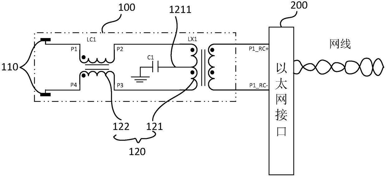
[0027] Such as figure 1 As shown, this embodiment provides an Ethernet signal transmission interface circuit, including a first transmission network 100 and an Ethernet interface 200, and the first transmission network 100 includes a first differential line pair 110 and an inductive signal transformer 120, so The inductive signal transformer 120 includes a pulse transformer 121 and a first common-mode transformer 122, and the two pins P1 and P4 at the first end of the first common-mode transformer 122 are connected to one of the first differential line pair 110 respectively. The two pins P2 and P3 of the second end of the first common mode transformer 122 are respectively connected to the two ends of the first winding of the pulse transformer 121, and the two ends of the second winding of the pulse transformer 121 are connected to In the Ethernet interface 200, the first winding of the pulse transformer 121 is provided with a first center tap 1211, and the first center tap 121...

Embodiment 2

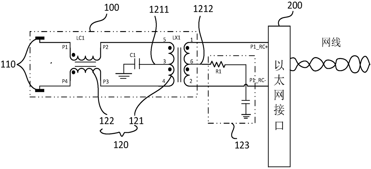
[0034] Such as figure 2 As shown, the difference between this embodiment and the previous embodiments is that the second winding of the pulse transformer 121 is provided with a second center tap 1212 , and the second center tap 1212 is connected to the Bob-Smith circuit 123 .

[0035] Adding Bob-Smith circuit 123 to the second center tap 1212 can help balance the network, eliminate EMI (electromagnetic interference) in Ethernet network signal transmission, isolate high voltage, suppress clutter, and impedance matching, making signal transmission more stable and complete; generally, the Bob-Smith circuit 123 includes two components - a resistor and a capacitor, one end of the second center tap 1212 is connected to the resistor, and the other end of the resistor is connected to the capacitor and then grounded, generally connected to the chassis ground. A 75-ohm resistor can be used for the resistor, and a 1nF / 2KV capacitor can be used for the capacitor.

Embodiment 3

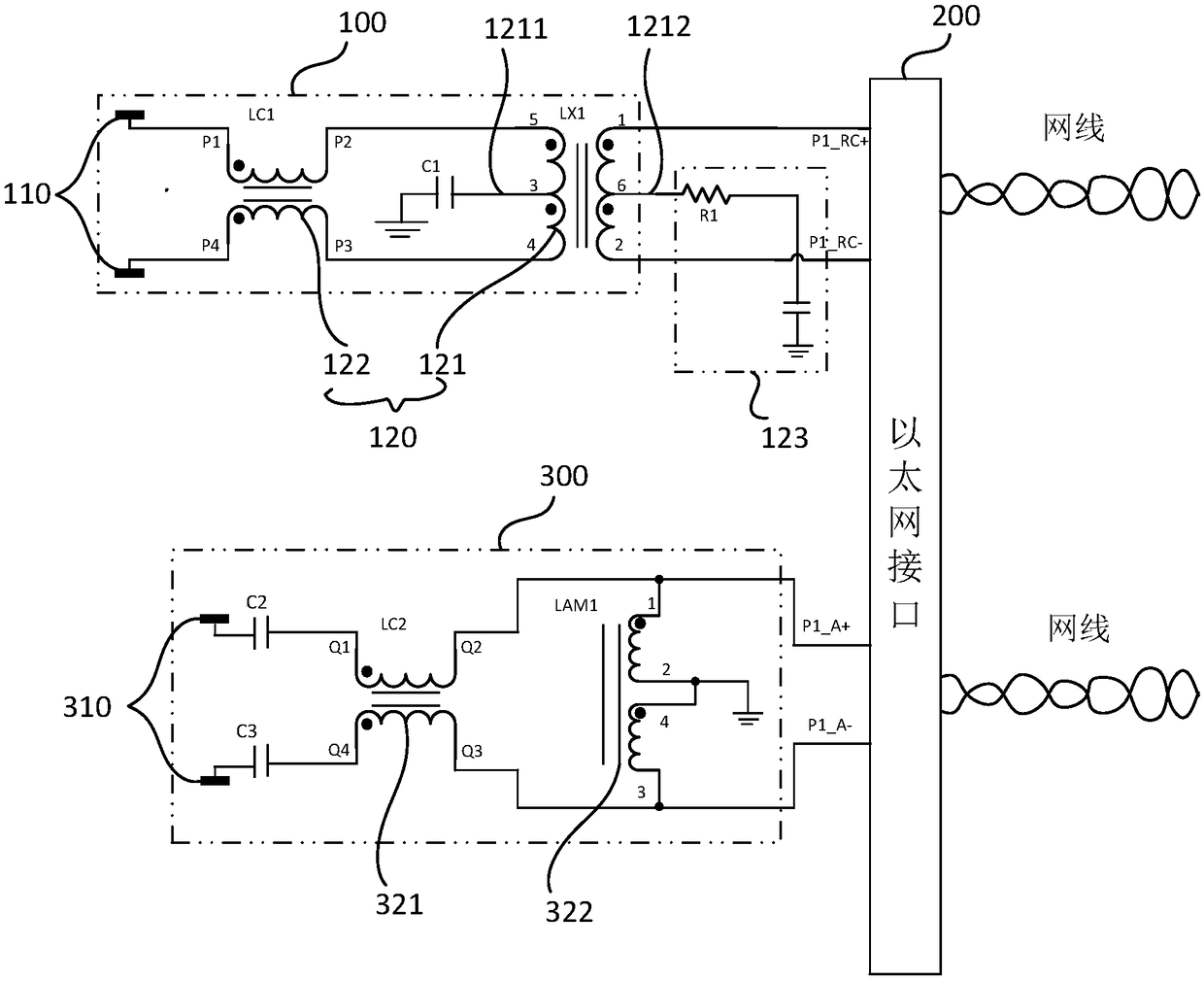
[0037] Such as image 3 , Figure 4 As shown, the difference between this embodiment and Embodiment 1 and Embodiment 2 is that the interface circuit provided by this embodiment further includes a second transmission network 300, and the second transmission network 300 includes a second differential line pair 310 and a capacitive A signal transformer, the second differential line pair 310 is connected to the Ethernet interface 200 through a capacitive signal transformer.

[0038] The reason why the second transmission network 300 is set is that not all differential lines are used to transmit power in POE transmission. Standard POE requires that the positive poles of 1 and 2 line pairs transmit power in the differential pair, and the negative poles of 3 and 6 line pairs transmit power; If the standard POE is used, the situation will be more. But in general, differential pairs can be divided into charged and uncharged differential pairs according to whether they have a DC power...


PUM


Abstract

The invention discloses an Ethernet signal transmission interface circuit, method and network equipment. The interface circuit comprises a first transmission network and an Ethernet interface, the first transmission network comprises a first differential line pair and an inductive signal transformer; the inductive signal transformer comprises a pulse transformer and a first common-mode transformer; two pins at the first end of the first common-mode transformer are respectively connected with a differential line in the first differential line pair, two pins at the second end of the first common-mode transformer are respectively connected with two ends of a first winding of the pulse transformer, two ends of the second winding of the pulse transformer are connected with the Ethernet interface; a first center tap is arranged at the first winding of the pulse transformer, and the first center tap is grounded through the first capacitor. The interface circuit can be applied to the POE transmission, and is capable of singly realizing the transmission of a pair of differential signals, the diversification circuit combined design can be performed according to the data receiving or transmission demand of each contact of the Ethernet interface, and the adaptability of the Ethernet interface can be enhanced.

Description

technical field [0001] The invention relates to the technical field of communication, and in particular designs an Ethernet signal transmission interface circuit, method and network equipment. Background technique [0002] POE (Power Over Ethernet) refers to the use of IP-based terminals (such as IP phones, wireless LAN access points AP, network cameras) without any changes to the existing Ethernet Cat. etc.) while transmitting data network signals, it can also provide DC power supply technology for such devices. POE is also known as a local area network-based power supply system (POL, Power over LAN) or Active Ethernet (Active Ethernet), sometimes referred to as Power over Ethernet, which uses existing standard Ethernet transmission cables to simultaneously transmit data and The latest standard specification of electrical power, and maintain compatibility with existing Ethernet systems and users. [0003] The current way of transmitting POE is mainly realized by an isolat...

Claims


Application Information

Patent Timeline
IPC IPC(8): H04L12/28H04L12/02H04L12/10
CPCH04L12/02H04L12/10H04L12/28
Inventor 陈建龙罗冬平王玮琪
Owner 台州市吉吉知识产权运营有限公司
Why Eureka
Try Eureka