Milling method of high-precision suspended web

A high-precision, web technology, applied in milling machine equipment, milling machine equipment details, metal processing equipment, etc., can solve problems such as low efficiency, large deformation, poor surface quality, etc., achieve high efficiency, reduce cutting force, and reduce cutting residue volume effect

Active Publication Date: 2018-11-06
CHENGDU AIRCRAFT INDUSTRY GROUP
View PDF6 Cites 20 Cited by
  • Summary
  • Abstract
  • Description
  • Claims
  • Application Information

AI Technical Summary

Problems solved by technology

[0007] Aiming at the problems of low efficiency, large deformation and poor surface quality of the existing large-size suspended web, the present invention proposes an efficient and high-quality numerical control machining method suitable for smooth suspended web

Method used


Image

  • Milling method of high-precision suspended web
  • Milling method of high-precision suspended web
  • Milling method of high-precision suspended web

Examples


Embodiment 1

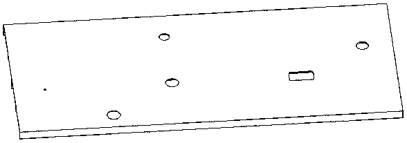
[0030] A milling method of a high-precision suspended web according to the present invention, the first step: rough milling the smooth surface of the part, leaving a process margin of 3~4mm, and using a milling cutter with a diameter of ≥30mm.

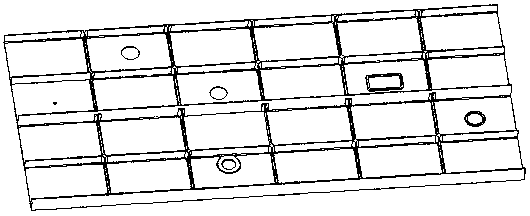
[0031] Step 2: Roughly mill the frame surface of the part, set the supporting process boss 2 in the center of the cavity 1 of the frame surface, the height of the supporting process boss 2 is the same as the height of the positioning rib edge, and leave a process margin of 3~ for the rest of the frame surface of the part 4mm.

[0032] Step 3: Repair the reference without stress, with the smooth surface of the part facing down, use gaskets to cover the gap caused by the deformation of the part, then press the part, mill the positioning rib and the top surface of the supporting process boss 2 to form a positioning reference noodle.

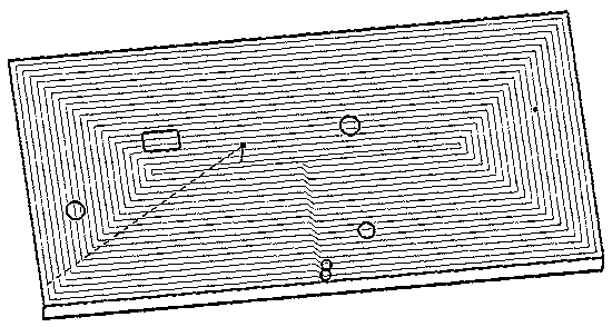
[0033] Step 4: Semi-finish milling smooth web, milling to remove the process allowance of the web part. ...

Embodiment 2

[0044]The present invention proposes a setting method for supporting process bosses 2 suitable for large-scale high-precision suspended web processing. The numerical control processing process is divided into rough milling smooth surface, rough milling frame surface, stress-free repair reference, and semi-finish milling smooth web , fine milling smooth web, rough milling frame surface process boss, fine milling frame surface and other stages, the specific implementation content and precautions are as follows:

[0045] 1) Rough milling smooth surface

[0046] There is a process allowance of 3~4mm, and the processing tool D≥32.

[0047] 2) Rough milling frame surface

[0048] The support process boss 2 and the process allowance 3 are left. After the part is turned over, the support process boss 2 participates in the positioning, and the processing effect of the frame surface is as follows: Figure 4 shown. According to the large size and weak rigid structure characteristics o...


PUM


Abstract

The invention discloses a milling method of a high-precision suspended web. The milling method is used for efficient and stable milling of a large-size suspended web structure and comprises the stepsthat the glossy face of a part is subjected to rough milling, and the technical allowance is reserved; a frame face is subjected to rough milling, the technical allowance is reserved, and a pluralityof false bosses are reserved according to the structural characteristics, so that the structural rigidity of the part is improved; the frame face is pressed in an unstressed mode, a positioning datumface is corrected, and thus the situation that the machining error is caused by part deformation is prevented; a glossy face web is subjected to semi-fine milling, and the small allowance is reserved;and the glossy face web is subjected to finish machining in place in modes of a small-diameter tool in small cutting quantity and back-and-forth feed, and thus the situations that cutter back-off deformation is caused by the large cutting quantity, and the surface quality of a part becomes poor due to trajectory change and acceleration and deceleration of a machine tool are prevented. The millingstability of the large-size suspended web structure is effectively improved, the part machining efficiency and the surface quality integrity are improved, and reworking polishing of a bench worker isreduced.

Description

technical field [0001] The invention relates to the technical field of mechanical processing, in particular to the milling processing technology of a suspended web. Background technique [0002] With the development of aviation technology, the performance indicators of modern aircraft such as maneuverability, flight performance, life and low manufacturing cost have been continuously improved, and aviation structural parts have gradually developed in the direction of large-scale, integrated, and thin-walled. Taking the lower beam of the fuselage side of the aircraft as an example, this type of parts has gradually adopted an integral design. Compared with the traditional process of riveting several short beams, the new design has strong integrity, high reliability, light weight, and small deformation. Features. The side beam parts are large in size and have a double-sided structure, one side of which is a smooth structure ( figure 1 shown), the other side is the frame struct...

Claims


Application Information

Patent Timeline
Patent Type & Authority Applications(China)
IPC IPC(8): B23C3/00
CPCB23C3/00B23C2215/04
Inventor 刘元吉姜振喜黄明聪方雨舟廖双权杨京京
Owner CHENGDU AIRCRAFT INDUSTRY GROUP
Why Eureka
Try Eureka