Precise grinding processing method of aspheric array structure
A technology of array structure and processing method, which is applied in the field of precision manufacturing, can solve the problems that cannot be used for processing aspheric array structures, etc., and achieve the effect of high-precision processing
- Summary
- Abstract
- Description
- Claims
- Application Information
AI Technical Summary
Problems solved by technology
Method used
Image
Examples
specific Embodiment approach 1
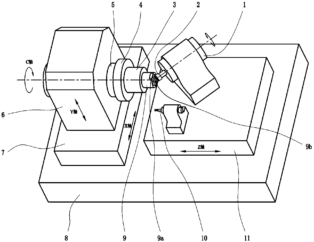
[0032] This embodiment is directed to a concave aspheric array structure, and is characterized in that the surface shape of the aspheric array sub-unit processed by the present invention is concave. The schematic diagram of the processing device is as figure 1 shown. Realize the present invention needs to adopt as figure 1 The four-axis linkage processing machine shown includes three translational axes, X-axis 7, Y-axis 6, and Z-axis 11, and an angle-controllable workpiece spindle C-axis 5. In addition, the machine tool needs to be equipped with a high-speed tool spindle 1 and a set of in-situ measuring devices 10, which are respectively used to drive the high-speed rotation of the grinding wheel and realize the measurement of the surface profile of the aspheric array subunit.
[0033] The specific steps of processing the concave aspheric array structure include:
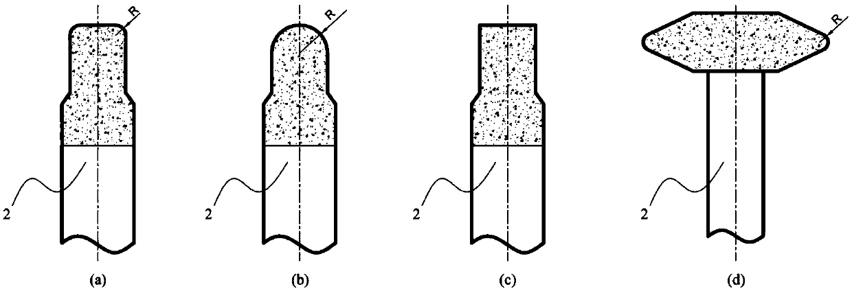
[0034] Step 1. Select as image 3 Any one of the grinding wheels 2 in (a), 3(b), and 3(c) is installed on the h...
specific Embodiment approach 2
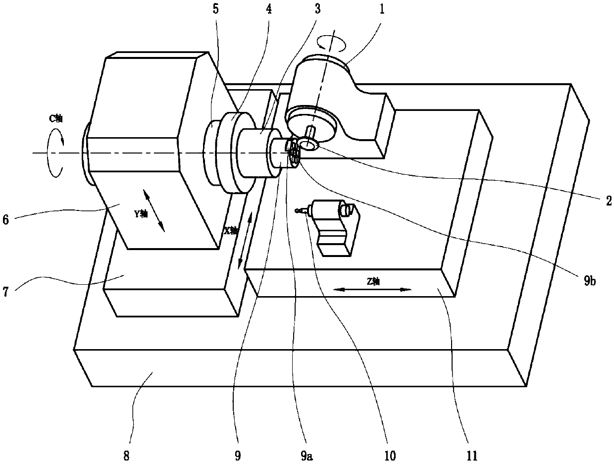
[0055] This embodiment is directed to a convex aspheric array structure, and is characterized in that the surface shape of the aspheric array sub-unit processed by the present invention is convex. The schematic diagram of the processing device is as figure 2 shown. This embodiment is basically the same as the specific embodiment 1, except for the following two points of difference:
[0056] 1. In step 1, you should select such as image 3 As shown in (d), the V-shaped grinding wheel with a tip arc is installed on the high-speed tool spindle 1, and the axis of the tool spindle must be perpendicular to the axis of the workpiece spindle;
[0057] 2. In step 34, R is the tip arc radius of the V-shaped grinding wheel with tip arc.
Embodiment 1
[0059] In a specific implementation process, a concave aspheric array mold core is ground. The aperture size of the subunits of the lens array is 2mm, arranged in a 2×2 square, and the subunit pitch is 1.25mm. The processing equipment is the five-axis ultra-precision machining machine tool FG650 produced by MooreNanotechnology Company; the mold core material is tungsten carbide; the #325 rounded columnar resin bonded diamond grinding wheel is used for rough grinding, and the #2400 rounded columnar resin bonded diamond grinding wheel is used for rough grinding. For precision and compensation grinding, the fillet radius r of the grinding wheel is 0.15mm, and the diameter D is 2mm; the rotation speed of the grinding wheel is 45000rpm, the rotation speed of the workpiece is 8rpm, and the feed distance is 2μm. The initial processing trajectory of the grinding wheel is obtained by using the process introduced in this method. Figure 5 shown. After the first fine grinding, the in-si...
PUM
| Property | Measurement | Unit |
|---|---|---|
| Corner radius | aaaaa | aaaaa |
Abstract
Description
Claims
Application Information
 - R&D
- Intellectual Property
- Life Sciences
- Materials
- Tech Scout
- Unparalleled Data Quality
- Higher Quality Content
- 60% Fewer Hallucinations
Browse by: Latest US Patents, China's latest patents, Technical Efficacy Thesaurus, Application Domain, Technology Topic, Popular Technical Reports.
© 2025 PatSnap. All rights reserved.Legal|Privacy policy|Modern Slavery Act Transparency Statement|Sitemap|About US| Contact US: help@patsnap.com


