
Deep well cross-hole underground water flow rate, flow direction and geological parameter determining device and method

A technology of geological parameters and measuring devices, which is applied in the fields of electric/magnetic detection and measurement for well logging records, earthwork drilling and mining, etc., which can solve the problems of scarcity of radioactive tracers, personal health and environmental damage of staff, and easy Radioactive accidents and other problems occur, to achieve the effect of simple and convenient measurement process, wide applicability and low cost

Pending Publication Date: 2018-11-06
ANHUI UNIV OF SCI & TECH
View PDF6 Cites 7 Cited by
  • Summary
  • Abstract
  • Description
  • Claims
  • Application Information

AI Technical Summary

Problems solved by technology

However, the isotope single-hole dilution test is a radioactive operation during the tracer injection process. The storage of radioisotopes, on-site injection, protection, testing, and the cooperation of auxiliary personnel are prone to radioactive accidents, which have extremely serious consequences for the personal health of the staff and the environment. injury, and the types of radioactive tracers are rare, and it is necessary to re-inspect whether it is applicable before each use, and there are certain limitations

Method used


Image

  • Deep well cross-hole underground water flow rate, flow direction and geological parameter determining device and method
  • Deep well cross-hole underground water flow rate, flow direction and geological parameter determining device and method
  • Deep well cross-hole underground water flow rate, flow direction and geological parameter determining device and method

Examples


Embodiment Construction

[0034] The following will clearly and completely describe the technical solutions in the embodiments of the present invention with reference to the accompanying drawings in the embodiments of the present invention. Obviously, the described embodiments are only some, not all, embodiments of the present invention. Based on the embodiments of the present invention, all other embodiments obtained by persons of ordinary skill in the art without making creative efforts belong to the protection scope of the present invention.

[0035] The object of the present invention is to provide a deep well cross-hole groundwater flow velocity flow direction and geological parameter measurement device and method to solve the problems in the prior art above, and to measure the groundwater flow velocity, flow direction and related parameters efficiently, quickly, accurately and without radioactive pollution. Determination of groundwater hydrogeological parameters.

[0036] In order to make the abo...


PUM


Abstract

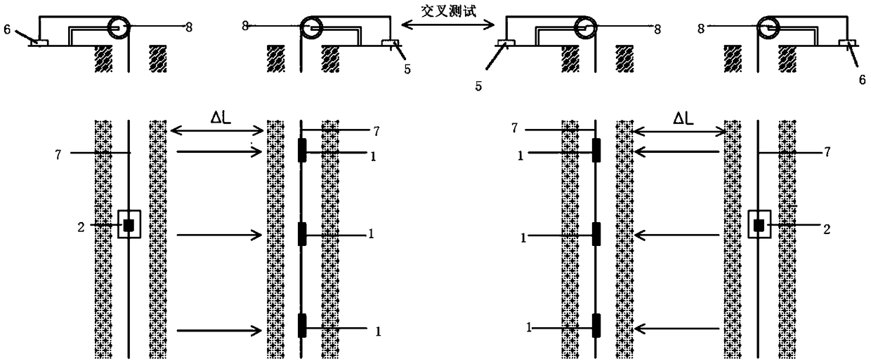
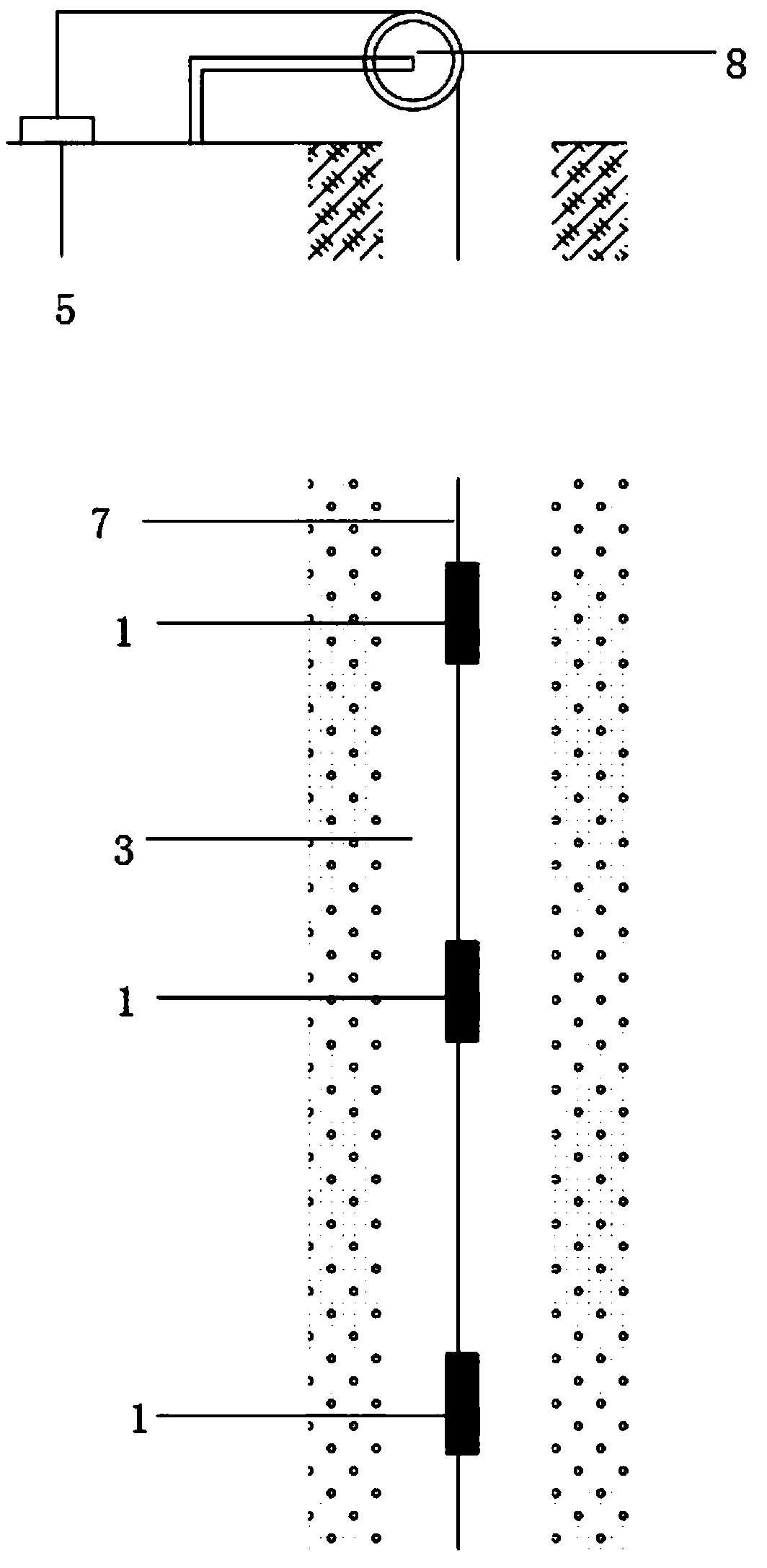
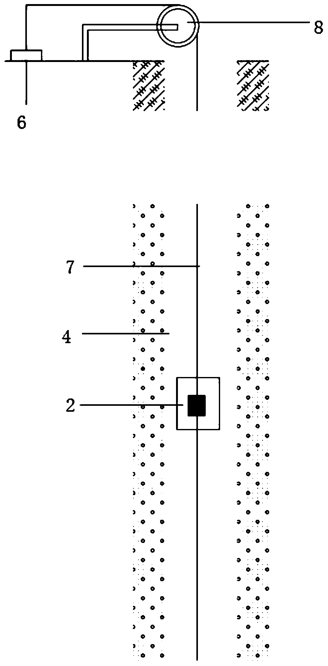
The invention discloses a deep well cross-hole underground water flow rate, flow direction and geological parameter determining device. The determining device comprises a detector and a source injector, wherein the detector is connected with a data collection instrument, and the source injector is connected with a source-injecting control instrument. A method adopting the device comprises the following steps that the corresponding relationship between the conductivity and the concentration of a tracer material solution at different temperatures is determined; at least two drilling holes are selected; a target aquifer section is selected; the detector is lowered into the target aquifer section in a hole to test the conductivity background value and the temperature value; the source injectoris used to inject the tracer material solution into a source-injecting hole, and the detector is used to measure the water conductivity and the temperature in the detecting hole, so that obtain a distribution curve of the solubility of the tracer material solution with time is obtained; and a crossed test is carried out to calculate and obtain the seepage velocity and the flow direction of the underground water in the holes. The deep well cross-hole underground water flow rate, flow direction and geological parameter determining method can rapidly complete the determination of the undergroundwater flow rate, flow direction and related hydrogeological parametric of the underground water without radioactive pollution.

Description

technical field [0001] The invention relates to the technical field of groundwater parameter measurement, in particular to a deep well cross-hole groundwater flow velocity and flow direction and geological parameter measurement device and method. Background technique [0002] Groundwater velocity and flow direction are two important dynamic parameters in the study of groundwater seepage field, and are the basis for determining the permeability coefficient and seepage volume of aquifers. With the rapid development of underground engineering, more and more engineering construction needs to master the basic parameters of groundwater seepage in order to solve the possible hidden dangers of accidents, such as deep well grouting diffusion process, detection of reservoir seepage inlet, river embankment Piping leakage, mine water disaster prevention, road bridge and culvert slope seepage, underground railway hydrogeological survey and monitoring, excavation and drainage of foundatio...

Claims


Application Information

Patent Timeline
IPC IPC(8): E21B47/00E21B47/11E21B49/00
CPCE21B47/00E21B49/00E21B47/11G01V3/30E21B47/113E21B49/0875E21B47/07G01V3/20
Inventor 张平松程桦姚直书许光泉荣传新李圣林
Owner ANHUI UNIV OF SCI & TECH
Learn More