Compound shaft sleeve structure of magnetic suspension motor rotor

A motor rotor and composite technology, applied in shafts, bearings, bearing components, etc., can solve the problems of environmental protection and resource saving, difficult nickel-based alloy processing, complex processing technology, etc., to reduce material costs, low parts costs, The effect of high cutting speed

Pending Publication Date: 2018-11-06
NANJING CIGU TECH CORP LTD
View PDF6 Cites 3 Cited by
  • Summary
  • Abstract
  • Description
  • Claims
  • Application Information

AI Technical Summary

Problems solved by technology

[0012] Considering the above requirements comprehensively, only some nickel-based alloys can fully meet the performance requirements, but the price of these nickel-based alloys is 10 to 20 times that of alloy steel commonly used for shaft parts; and the processing of nickel-based alloys is very difficult and the processing technology is complicated; At the same time, the large amount of alloying elements used in the alloy will also waste valuable industrial resources, which is not conducive to environmental protection and resource conservation.

Method used


Image

  • Compound shaft sleeve structure of magnetic suspension motor rotor

Examples


Embodiment Construction

[0026] The present invention will be further described below in conjunction with the accompanying drawings.

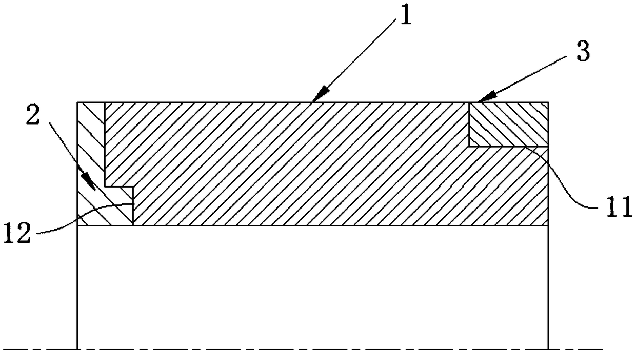
[0027] Such as figure 1 As shown, the present invention discloses a composite shaft sleeve structure of a magnetic levitation motor rotor, including a transition sleeve body 1, a magnetic isolation ring 2 and a detection ring 3, and the magnetic isolation ring 2 and the detection ring 3 are respectively arranged on two ends of the transition sleeve body 1. Side, and between the magnetic isolation ring 2 and the transition sleeve body 1 and between the detection ring 3 and the transition sleeve body 1 are all interference fits.

[0028] The detection ring 3 is sleeved on the transition sleeve body 1, and the outer wall surface of the detection ring 3 is flush with the outer wall surface of the transition sleeve body 1; one end of the magnetic isolation ring 2 is installed in the transition sleeve body 1, and the The outer wall surface is flush with the outer wall surfa...


PUM


Abstract

The invention discloses a compound shaft sleeve structure of a magnetic suspension motor rotor. The compound shaft sleeve structure comprises a transition sleeve body, a magnetism isolating ring and adetection ring. The magnetism isolating ring and the detection ring are separately arranged on two sides of the transition sleeve body and are in interference fit to the transition sleeve body; the detection ring is arranged on the transition sleeve body in a sleeving mode, and the outer wall surface of the detection ring is aligned to the outer wall surface of the transition sleeve body; one endof the magnetism isolating ring penetrates the transition sleeve body and the outer wall surface of the magnetism isolating ring is aligned to the outer wall surface of the transition sleeve body; the transition sleeve body is made from high alloy steel, the magnetism isolating ring is made from austenitic stainless steel, and the detection ring is made from a nickel-based alloy. By utilizing thecharacteristics of different materials reasonably, the materials draw on each other's strength through a structural design, so that the integral optimum performance is achieved. The compound shaft sleeve structure is low in cost of parts and easy to produce, and the output is improved.

Description

Technical field: [0001] The invention relates to a composite shaft sleeve structure of a magnetic levitation motor rotor. Background technique: [0002] The rotor structure of the magnetic levitation high-speed permanent magnet motor is relatively complex, and there are often high requirements for the performance of various aspects of the core shaft material, which leads to difficult material selection and high material prices. [0003] The mandrel transition sleeve is one of the more typical parts. The mandrel transition sleeve has a simple shape and is a thick-walled hollow cylinder. But its material needs to take into account different performance requirements: [0004] 1) Since one end needs to contact the permanent magnet of the rotor, the material is required to be non-magnetic; [0005] The magnetically permeable material will cause magnetic flux leakage between the poles of the permanent magnet, thereby reducing the effective magnetic flux of the rotor of the perma...

Claims


Application Information

Patent Timeline
Patent Type & Authority Applications(China)
IPC IPC(8): F16C33/06
CPCF16C33/06F16C2204/52
Inventor 胡思宁吴立华董继勇
Owner NANJING CIGU TECH CORP LTD
Why Eureka
Try Eureka