Mini type turbine engine combustion chamber

A micro-turbine and combustion chamber technology, applied in the direction of combustion chambers, continuous combustion chambers, combustion methods, etc., can solve the problems of ignition instability and achieve the effects of improving ignition stability, easy ignition, and simple structure

Pending Publication Date: 2018-11-06
西安空天能源动力智能制造研究院有限公司
View PDF7 Cites 3 Cited by
  • Summary
  • Abstract
  • Description
  • Claims
  • Application Information

AI Technical Summary

Problems solved by technology

In a gas turbine engine, the evaporator tube combustor is generally designed with a Г-shaped or T-shaped evaporator tube. For a micro engine, the evaporator tube is mostly a vertical evaporator tube. The design of the opening; the existing micro-turbine engine evaporator tube combustion chamber adopts the method of direct ignition in the combustion chamber, and its ignition success is directly affected by the airflow velocity at the ignition point, and the ignition is often unstable

Method used


Image

  • Mini type turbine engine combustion chamber
  • Mini type turbine engine combustion chamber
  • Mini type turbine engine combustion chamber

Examples


specific Embodiment approach

[0027] It should be noted that the structures, proportions, sizes, etc. shown in the drawings attached to this specification are only used to match the content disclosed in the specification, for those who are familiar with this technology to understand and read, and are not used to limit the implementation of the present invention Any modification of the structure, change of the proportional relationship or adjustment of the size shall still fall within the scope of the technical content disclosed in the present invention without affecting the effect and the purpose of the present invention. within the scope covered.

[0028] Also, it is to be understood that the terms "central", "longitudinal", "transverse", "upper", "lower", "front", "rear", "left", "right", "vertical", " The orientations or positional relationships indicated by "horizontal", "top", "bottom", "inner", "outer", etc. are based on the orientations or positional relationships shown in the drawings, and are only...

Embodiment 1

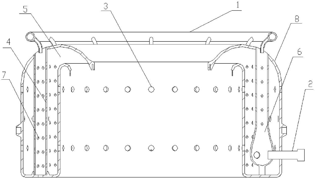
[0032] Such as figure 1 Shown, a kind of microturbine engine combustor comprises oil transfer ring 1, igniter 2 evaporation tube 4 and combustor housing 8,

[0033] Wherein, the outer wall of the combustion chamber housing 8 is provided with a combustion chamber intake hole 3, which is used to enter the high-pressure airflow outside the combustion chamber into the combustion chamber through the combustion chamber intake hole 3, and the lower area of ​​the combustion chamber housing 8 outer wall Extending to the inside of the body and bending to form an inner wall, the outer wall and the inner wall form an annular U-shaped cavity, which is the combustion chamber cavity 5, and a through hole is opened on the inner wall. The oil transfer ring 1 belongs to the fuel system and is connected to the external pipeline The oil delivery pipe under the oil delivery ring 1 is welded to the upper end of the combustion chamber housing 8 through a metal connecting piece, and the end of the oi...

Embodiment 2

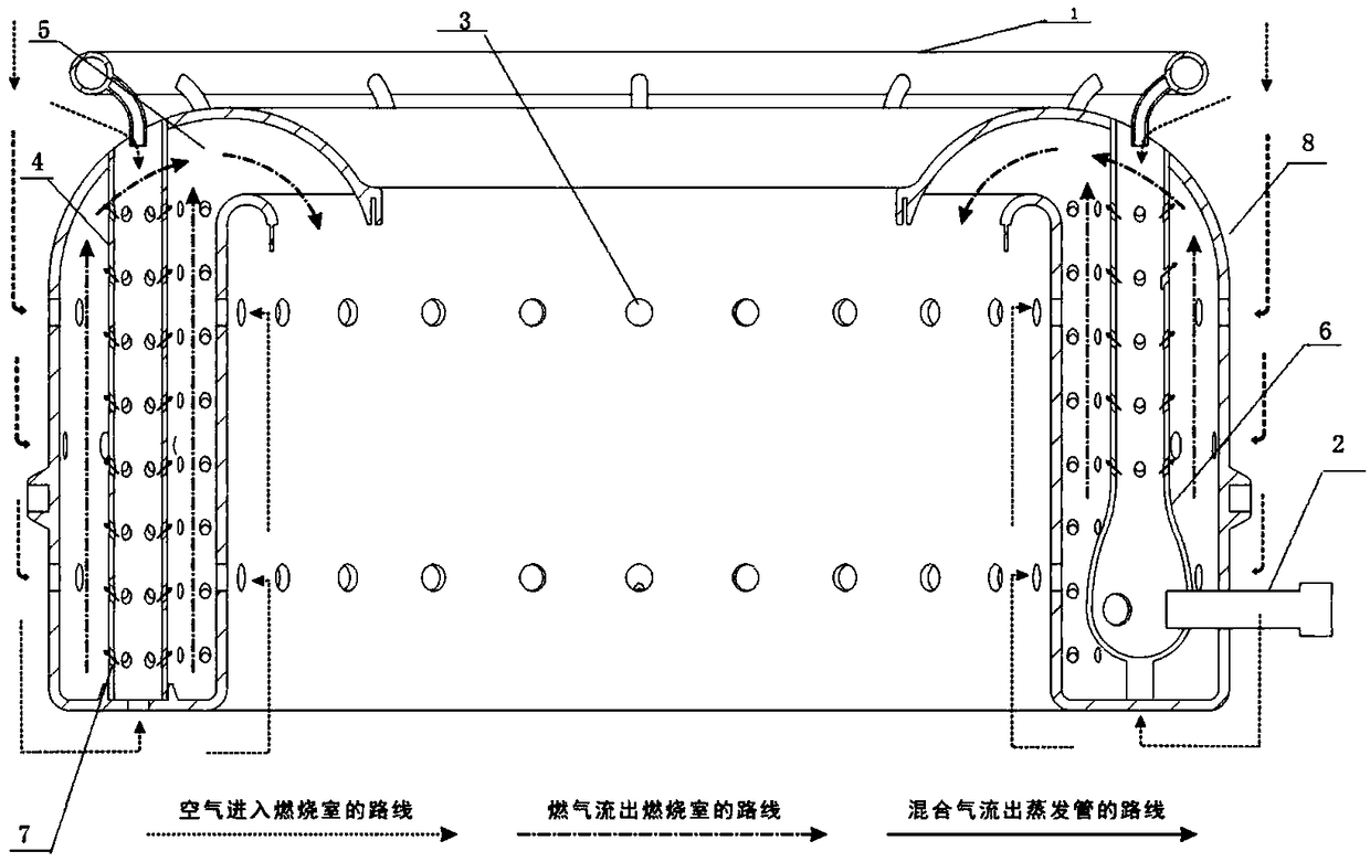
[0037] Such as Figure 1-5 Shown, a kind of microturbine engine combustor, comprises oil transfer ring 1, igniter 2, combustion chamber intake hole 3, evaporation pipe 4 and combustion chamber housing 8,

[0038] Wherein, the outer wall of the combustion chamber housing 8 is provided with a combustion chamber intake hole 3, which is used to enter the high-pressure airflow outside the combustion chamber into the combustion chamber through the combustion chamber intake hole 3, and the lower area of ​​the combustion chamber housing 8 outer wall Extend and bend to the inside of the body to form an inner wall. The outer wall and the inner wall form an annular U-shaped cavity, which is the combustion chamber cavity 5. There are through holes on the inner wall. The oil transfer ring 1 is fixedly connected to the The upper end of the combustion chamber housing 8 and the end of the oil delivery pipe are placed inside the combustion chamber cavity 5. The oil delivery ring 1 belongs to t...


PUM


Abstract

The invention provides a mini type turbine engine combustion chamber. The mini type turbine engine combustion chamber comprises an oil conveying ring, an igniter, evaporation pipes, a combustion chamber shell and a combustion chamber ignition cavity. Combustion chamber air inlet holes are formed in the outer wall of the combustion chamber shell. After the lower area of the outer wall of the combustion chamber shell extends into the body and is bent, an inner wall is formed, and an annular U-shaped cavity is formed by the outer wall and the inner wall and is a combustion chamber cavity. The oilconveying ring is fixedly connected to the upper end of the combustion chamber shell, the tail end of an oil conveying pipe is arranged in each evaporation pipe, and the igniter is arranged on the side wall of the combustion chamber shell. The multiple evaporation pipes are fixedly connected in the combustion chamber cavity. The injection action of high-temperature and high-pressure airflow in the combustion chamber is utilized for bringing out fuel oil and air mixed gas in the evaporation pipes, and combustion in the combustion chamber is more uniform; and meanwhile, the independent ignitioncavity is used in the combustion chamber, and ignition stability is improved.

Description

technical field [0001] The invention belongs to the field of gas turbine engine combustion chambers, and relates to a micro turbine engine combustion chamber. Background technique [0002] A gas turbine engine generally consists of five major components, which are the intake port, compressor, combustion chamber, turbine, and exhaust nozzle. The combustion chamber is one of the main components of a gas turbine engine, and its performance indicators are closely related to the overall performance indicators of the engine. In a gas turbine engine, the evaporating tube combustor is generally designed with a Г-shaped or T-shaped evaporating tube. For a micro engine, the evaporating tube is mostly a vertical evaporating tube. The design of the opening; the existing micro-turbine engine evaporator tube type combustor all adopts the mode of direct ignition in the combustion chamber, and its ignition success is directly affected by the air velocity at the ignition point, and the ignit...

Claims


Application Information

Patent Timeline
Patent Type & Authority Applications(China)
IPC IPC(8): F23R3/16F23R3/32
CPCF23R3/16F23R3/32
Inventor 刘林涛胡金海宋志平张百灵姚远陈喆李小涛
Owner 西安空天能源动力智能制造研究院有限公司
Why Eureka
Try Eureka