Multi-optical axis automatic calibration system and multi-optical axis automatic calibration method

An automatic calibration, multi-optical axis technology, applied in the field of optical calibration, can solve the problems of high cost, unsuitable for field handling test, large size and so on

Pending Publication Date: 2018-11-06
西安微普光电技术有限公司
View PDF0 Cites 10 Cited by
  • Summary
  • Abstract
  • Description
  • Claims
  • Application Information

AI Technical Summary

Problems solved by technology

Generally, when optical systems with different wavelength bands are tested or calibrated for optical axis coaxiality, a wide-spectrum large-aperture collimator is used, but this type of equipment is expensive, complex in manufacturing process, and large in size, which is not suitable for field handling test

Method used


Image

  • Multi-optical axis automatic calibration system and multi-optical axis automatic calibration method
  • Multi-optical axis automatic calibration system and multi-optical axis automatic calibration method

Examples


Embodiment 1

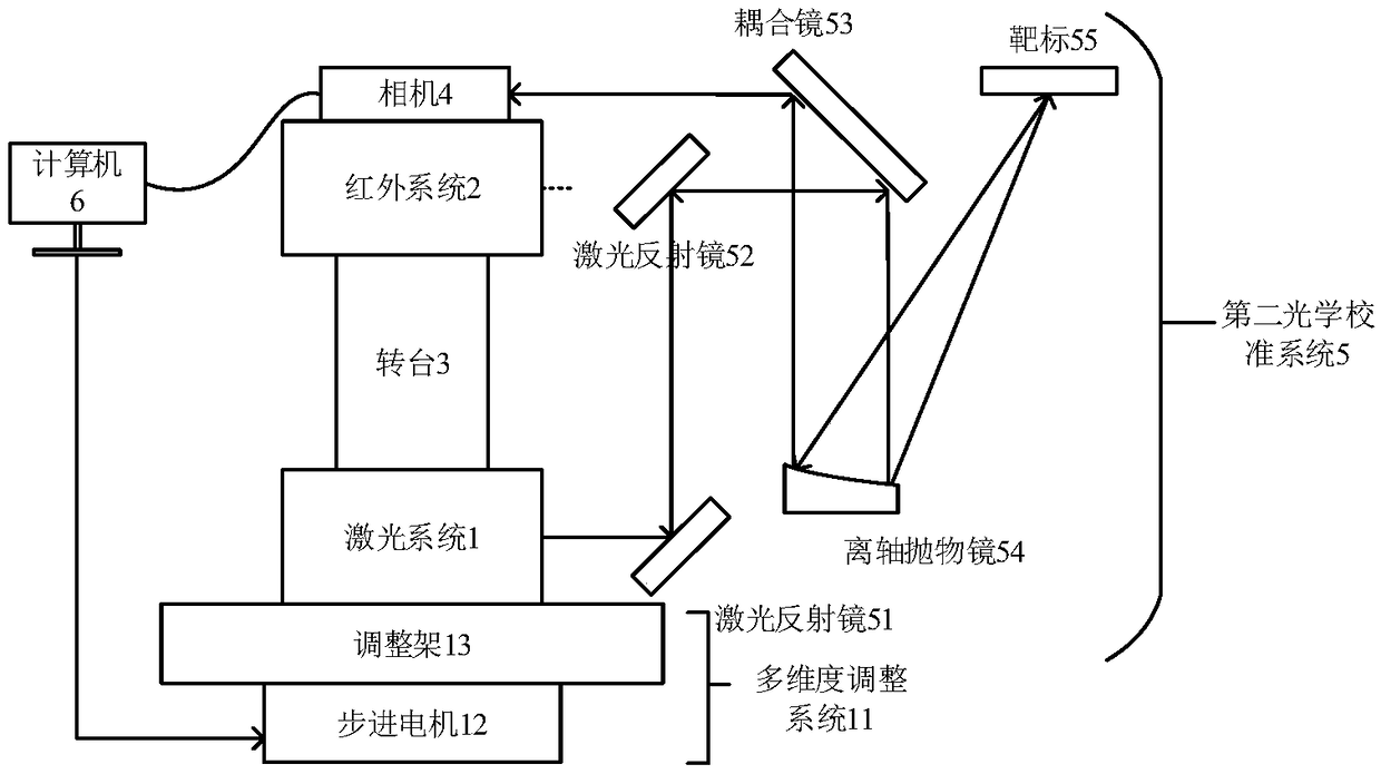
[0027] Such as Figure 1-2 As shown, a multi-optical axis automatic calibration system provided by the embodiment of the present invention includes: a near-infrared laser ranging system 1, which is installed on a multi-dimensional adjustment system 11; an infrared system 2, which communicates with the near-infrared A laser ranging system 1 is connected for determining the position of the target. In practical applications, the infrared laser ranging system 1, the infrared system 2 and the turntable 3 can rotate 360 ​​degrees without stopping, so that the infrared system 2 can find a target within a certain range around, and when a certain target is locked, the near Infrared laser ranging system 1 emits ranging laser beams to measure the actual distance of the target, which requires near-infrared laser ranging system 1 and infrared system 2 to have good coaxiality, otherwise it is difficult to obtain accurate measurement results.

[0028] The imaging system 4, usually using a v...

Embodiment 2

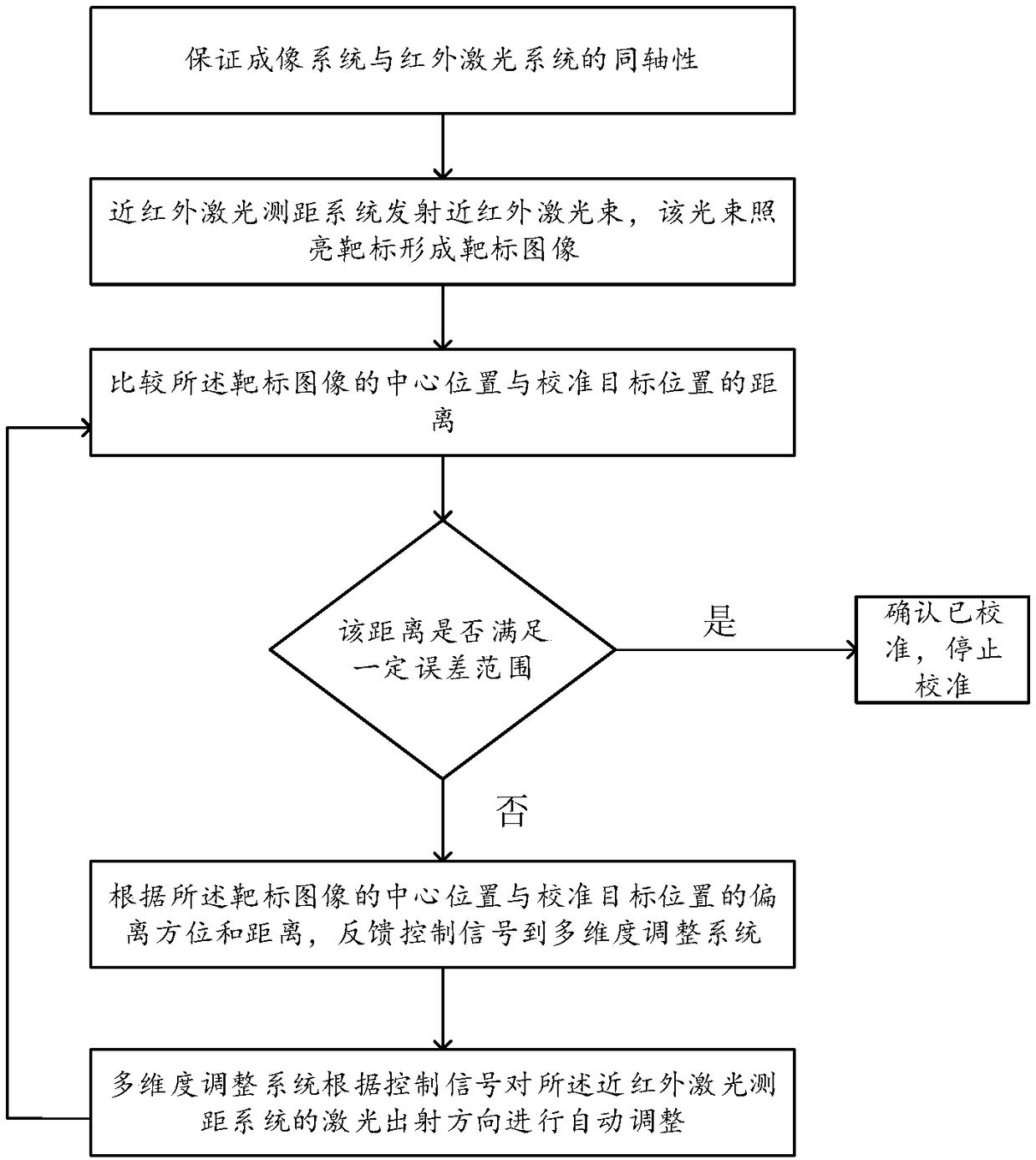
[0036] An embodiment of the present invention provides a multi-optical axis automatic calibration method, including: realizing the coaxiality between the imaging system 4 and the infrared system 2 through the first optical calibration system; the near-infrared laser ranging system 1 emits a near-infrared laser beam, and the beam The target 55 is illuminated after being reflected by the first laser reflector 51, the second laser reflector 52, the coupling reflector 53, and the off-axis parabolic mirror 54 in sequence; the light beam emitted by the illuminated target 55 passes through the off-axis parabola in sequence The mirror 54 and the coupling mirror 53 enter the imaging system 4 to form a target image; the computer system 6 compares the distance between the center position of the target image and the calibration target position; when the distance meets a certain error range, it is confirmed that it has been calibrated; Otherwise, according to the deviation azimuth and dista...


PUM


Abstract

The embodiment of the invention relates to a multi-optical axis automatic calibration system. The multi-optical axis automatic calibration system includes: a near-infrared laser ranging system (1) mounted on a multi-dimensional adjustment system (11); an infrared system (2) connected with the near infrared laser ranging system through a rotary table (3); an imaging system (4) fixedly connected with the infrared system; a second optical calibration system (5) used for calibrating the coaxiality of the near infrared laser ranging system (1) and the infrared system (2), and comprising: a first laser reflector (51), a second laser reflector (52), a coupling reflector (53), an off-axis parabolic mirror (54) and a target (55), wherein the first laser reflector (51), the second laser reflector (52), the coupling reflector (53) and the off-axis parabolic mirror (54) are respectively coated with a total reflection film with a corresponding wavelength; and a computer system (6) for analyzing theimage of the target and automatically adjusting the angle of the multi-dimensional adjustment system to the analysis result.

Description

technical field [0001] The invention relates to the field of optical calibration, in particular to a multi-optical axis automatic calibration system and method. Background technique [0002] With the complexity of the application environment, a single system is often unable to meet the complex use environment. The emergence of composite systems covering a wide spectral range has attracted more and more attention from various application levels. For the tracking and ranging of short-distance miniaturized targets, At present, the commonly used systems are long-wave infrared and near-infrared lasers. The infrared system is used to find the target, and the laser system measures the distance of the target. In this process, an important factor is the coaxiality of the infrared system and the laser system. Since the beam spread angle of the ranging laser is very small, when the target is far away, only the coaxiality of the infrared system and the laser system Well, the target can...

Claims


Application Information

Patent Timeline
IPC IPC(8): G01C25/00
CPCG01C25/00
Inventor 范哲源刘西站韩飞何飞
Owner 西安微普光电技术有限公司
Why Eureka
Try Eureka