
Motor power testing apparatus

A test device and power technology, applied in the field of motor power test devices, can solve the problems of increasing the difficulty of detection, inconvenient motor power detection, easy shaking, etc., and achieve the effects of convenient and intuitive observation, improved accuracy, and increased stability

Pending Publication Date: 2018-11-06
桐乡市龙翔众心纺织有限公司
View PDF0 Cites 1 Cited by
  • Summary
  • Abstract
  • Description
  • Claims
  • Application Information

AI Technical Summary

Problems solved by technology

[0003] When testing the power of the motor, the existing equipment needs to use tachometer and other equipment to detect the speed of the motor, and at the same time, it needs to calculate and analyze the data, which is troublesome and inconvenient to directly detect the power of the motor, which affects the accuracy of the test. The detection effect of the motor power, and when the motor power is detected, it is not easy to use motors of different sizes, which reduces the scope of application of the device, and needs to be replaced with different equipment for detection, which increases the difficulty of detection. Some devices are easy to shake when testing the motor, so it is difficult to observe the testing equipment, and it is inconvenient to quickly know the speed of the motor. Therefore, it is urgent to design a motor power testing device to solve the above problems

Method used


Image

  • Motor power testing apparatus

Examples


Embodiment Construction

[0016] The following will clearly and completely describe the technical solutions in the embodiments of the present invention with reference to the accompanying drawings in the embodiments of the present invention. Obviously, the described embodiments are only some, not all, embodiments of the present invention. Based on the embodiments of the present invention, all other embodiments obtained by persons of ordinary skill in the art without making creative efforts belong to the protection scope of the present invention.

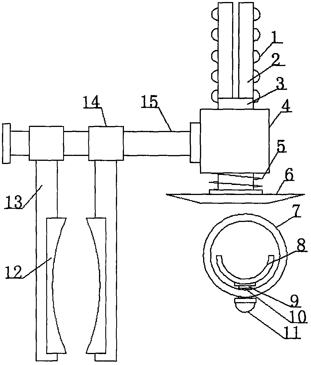
[0017] see figure 1 , the present invention provides a technical solution:

[0018] A motor power testing device, comprising a guide pipe 4, a connecting rod 15 is installed on the left side of the guide pipe 4, and a spiral tube 14 is sleeved on the surface of the connecting rod 15 symmetrically, and the connecting rod 15 is connected with the spiral tube 14 and the guide The pipe 4 is threaded, and the lower side of the spiral pipe 14 is fixedly equipped wi...


PUM


Abstract

The invention aims at disclosing a motor power testing apparatus so that a problem that the existing apparatus can not obtain the motor power visually, quickly and conveniently can be solved. The motor power testing apparatus is composed of a guide tube, a connecting rod, clamping plates, a spiral spring, mounting rods, a sleeving ring, and a screw rod. Solenoids sleeve the surface of the connecting rod symmetrically; anti-skid layers are installed on the inner side surfaces of the clamping plates fixedly; a sliding bar is arranged inside the spiral spring in a sleeving manner; a push plate isfixedly installed at the lower end of the sliding bar; and warning lights are installed on the surfaces of the mounting rods uniformly. A positioning ring is fixedly installed in the middle of the lower side wall of the sleeving ring. A locking plate is installed at the upper end of the screw rod; and a push block is fixedly installed at the lower end of the screw rod. According to the invention,the frequency of the motor rotation is obtained quickly by observing the frequency of the expose number changing of the warning lights, so that the motor power is observed visually and conveniently;and with the spiral spring, the sliding bar returns to the original position quickly and conveniently, so that the detection accuracy is improved. The motor power testing apparatus is worth popularizing.

Description

technical field [0001] The invention relates to the field of motor detection, in particular to a motor power testing device. Background technique [0002] The development of science and technology has put forward higher and higher requirements on the performance and quality indicators of motors. The development of motor testing technology is closely related to the development of motor industry. Motor test is an important part of comprehensive evaluation of motor assembly quality and technical performance, and an important process of motor manufacturing and production. Due to the long operation time of traditional test equipment and methods, many instruments need to be observed, and manual reading of test data and data analysis and calculation, the quality and accuracy of motor tests are affected to a certain extent. With the further improvement of the current motor design level and process level, as well as the continuous improvement of the performance of motor raw material...

Claims


Application Information

Patent Timeline
Patent Type & Authority Applications(China)
IPC IPC(8): G01R31/34
CPCG01R31/34
Inventor 钱裕珍
Owner 桐乡市龙翔众心纺织有限公司
Learn More