
Solid-state laser radar

A laser radar and solid-state technology, applied in the field of laser detection, can solve problems such as easy wear, high price, and difficult manufacturing

Pending Publication Date: 2018-11-06
SUTENG INNOVATION TECH CO LTD
View PDF9 Cites 3 Cited by
  • Summary
  • Abstract
  • Description
  • Claims
  • Application Information

AI Technical Summary

Problems solved by technology

[0004] However, the above-mentioned mechanical rotary laser radar has many disadvantages: the slip ring connecting the rotating part and the fixed part is easy to wear, which affects the service life of the entire device; the rotating part occupies a large volume, and it is difficult to further reduce the volume in future applications. Miniaturization; multi-line (such as 32-line, 64-line) lidar transmitter modules and receiver modules are set in pairs, which requires high angle settings and is difficult to manufacture, which is not conducive to mass production and is expensive

Method used


Image

  • Solid-state laser radar

Examples


Embodiment 1

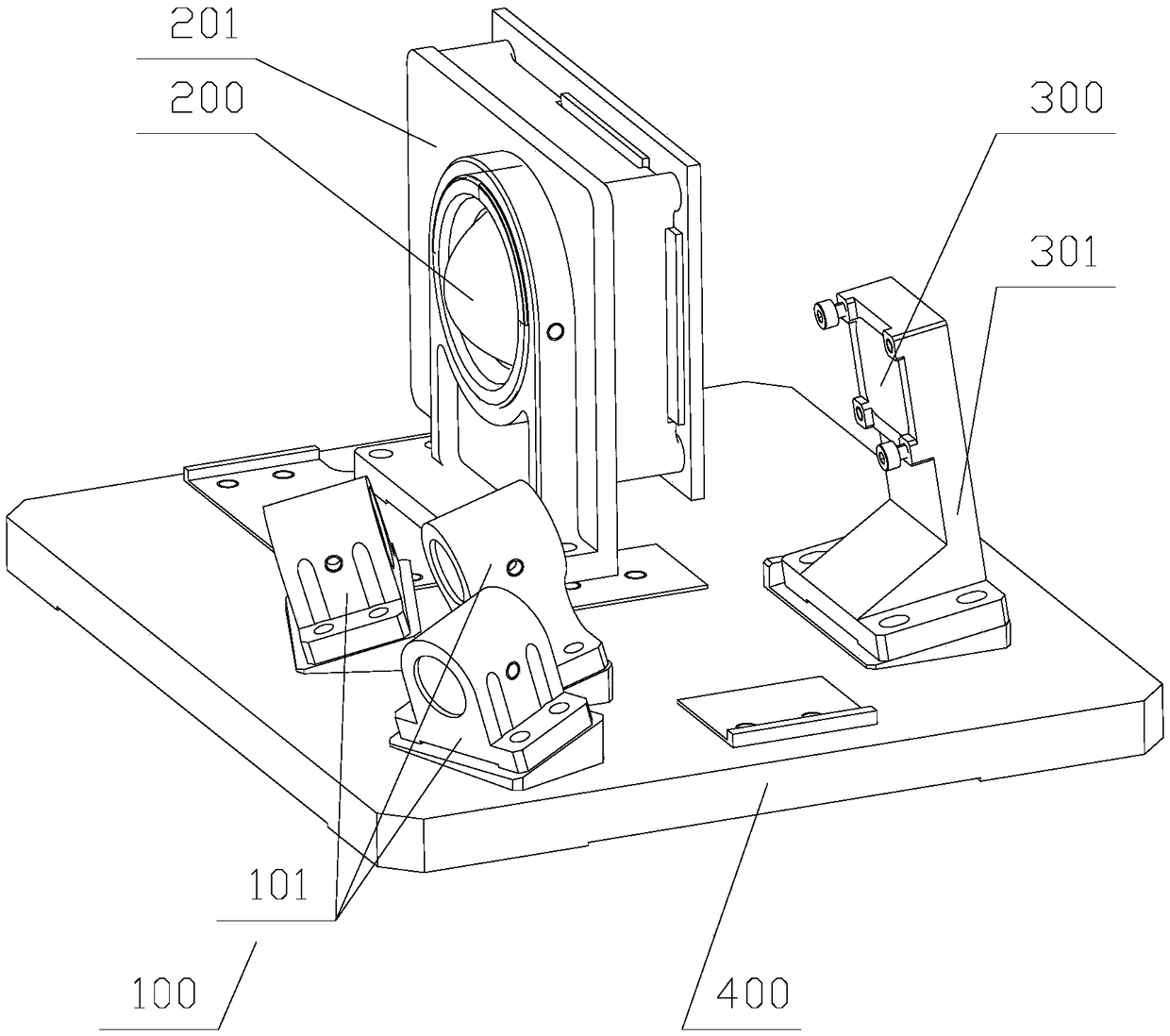
[0022] Such as figure 1 As shown, the solid-state lidar includes a transmitting component 100, a receiving component 200 and a MEMS device 300. The receiving component 200 is arranged on the left side of the transmitting component 100, and the MEMS device 300 is used to change the direction of the optical path of the laser emitted by the transmitting component 100.

[0023] It also includes a base 400 and a housing. The transmitting assembly 100, the receiving assembly 200 and the MEMS device 300 are all arranged in the cavity surrounded by the base 400 and the housing; the transmitting assembly 100, the receiving assembly 200 and the MEMS device 300 are fixed on the base 400.

[0024] The emitting assembly 100 includes three emitters 101; the emitted laser light of the emitters 101 has the same elevation angle α and is directed towards the MEMS device 300; the emitted laser light is directed upward toward the MEMS device 300, and after being reflected by the MEMS device 300, t...


PUM


Abstract

The invention discloses a solid-state laser radar, which comprises a transmitting assembly and a receiving assembly, wherein the receiving assembly is arranged at the lateral of the transmitting assembly. The solid-state laser radar further comprises an MEMS device which is used for changing the optical path direction of emitted laser of the transmitting assembly. The solid-state laser radar doesnot have any mechanical rotation part, adopts the MEMS device and is small and exquisite in structure and convenient to manufacture. The solid-state laser radar is reasonable in structural setting ofinternal devices, appropriate in operating space, convenient in installation and debugging and simplified in light shielding, and meets the use requirements of long-distance measurement and good receiving effects. The solid-state laser radar also has the characteristics of good stability, long service life, ability of being conducive to mass production, reasonable price and the like, and is suitable for large-scale commercial applications.

Description

technical field [0001] The invention relates to the technical field of laser detection, in particular to a solid-state laser radar. Background technique [0002] Lidar is a radar system that emits laser beams to detect the target's position, speed and other characteristic quantities. Its working principle is to first emit a detection laser beam to the target, then the receiver receives the signal reflected from the target, and finally the laser radar will reflect the signal. Compared with the transmitted signal, the relevant information of the target can be obtained after proper processing, such as target distance, azimuth, height, speed, attitude, and even shape and other parameters. [0003] Due to the inherent advantages of lidar for environmental perception, it has become the main sensor for autonomous driving technology to detect the environment. At present, the laser radar mainly adopts the mechanical rotation type: the rotating part drives the transmitting module and...

Claims


Application Information

Patent Timeline
Patent Type & Authority Applications(China)
IPC IPC(8): G01S7/481
CPCG01S7/4817
Inventor 邱纯鑫刘乐天
Owner SUTENG INNOVATION TECH CO LTD
Learn More