Flexible ultra-wideband MIMO antenna

An ultra-wideband and antenna technology, applied in the field of flexible ultra-wideband MIMO antennas, can solve the problems of low isolation and narrow frequency range, and achieve the effects of improving isolation, easy integration, and suppressing mutual coupling

Inactive Publication Date: 2018-11-06
XIDIAN UNIV
View PDF6 Cites 0 Cited by
  • Summary
  • Abstract
  • Description
  • Claims
  • Application Information

AI Technical Summary

Problems solved by technology

For example, the application publication number is CN 106282871 A, and the patent application titled "a compact four-element ultra-wideband MIMO antenna" discloses a compact four-element ultra-wideband MIMO antenna, which is provided with four identical radiating elements and four The same inverted L-shaped floor branches are respectively placed at the four corners of the dielectric board, and the long sides of the L-shaped floor branches coincide with the radiation unit to form a double-sided double microstrip line structure. There are two sets of floor gaps on the floor between adjacent radiating units. The S11 parameter is less than -10dB in the 3-10GHz frequency band, and the isolation is only about 15dB in the 3-10GHz frequency band. The antenna realizes miniaturization and ultra- Broadband characteristics, but the disadvantages are low isolation and narrow frequency range

Method used


Image

  • Flexible ultra-wideband MIMO antenna
  • Flexible ultra-wideband MIMO antenna
  • Flexible ultra-wideband MIMO antenna

Examples


Embodiment Construction

[0024] Below in conjunction with accompanying drawing and specific embodiment, the present invention is described in further detail:

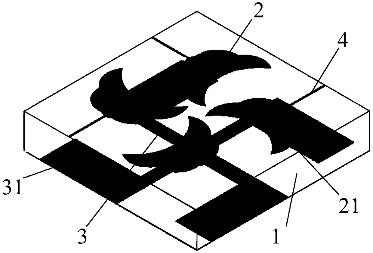
[0025] refer to figure 1 , a flexible ultra-wideband MIMO antenna proposed by the present invention includes a flexible film dielectric board 1 , a radiation unit 2 , a radiation floor 3 and a feeder 4 .

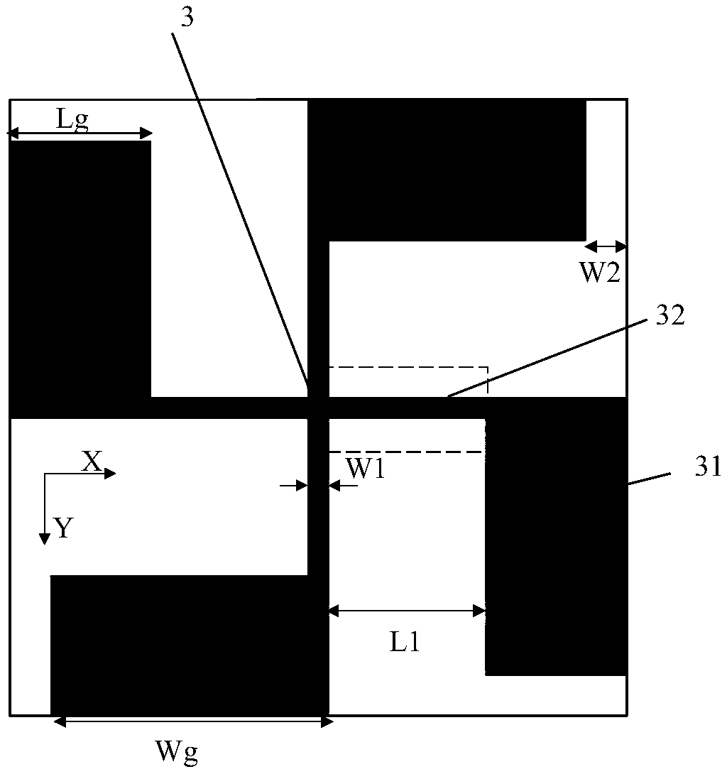
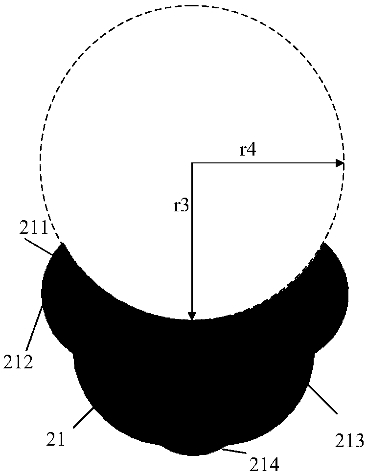
[0026] The radiation unit 2 adopts a centrosymmetric structure composed of four first radiation patches 21 , printed on the upper surface of the flexible film dielectric board 1 , and the central symmetry axis of the radiation unit 2 coincides with the central symmetry axis of the radiation floor 3 . The radiant floor 3 adopts a centrosymmetric structure composed of four second radiant patches 31 , which are printed on the lower surface of the flexible film dielectric board 1 . The flexible film dielectric plate 1 is made of Kapton flexible film material, and the relative permittivity ε r =3.4, the overall size is 65mm×65mm×0.125mm.

[002...


PUM


Abstract

The invention provides a flexible ultra-wideband MIMO antenna, which is used for improving the isolation degree of the ultra-wideband MIMO antenna, expanding the frequency band range of the antenna, comprising a flexible thin film dielectric plate (1), a radiation unit (2) printed on the upper surface of the dielectric plate and a radiation floor (3) printed on the lower surface of the dielectricplate. The radiating unit (2) adopts a center symmetrical structure composed of four first radiating patches (21), wherein the first radiating patch (21) is formed by splicing a plurality of circulararc curves, and each first radiating patch (21) is connected with a feed line (4); the radiation floor (3) adopts a centrally symmetrical structure consisting of four second radiation patches (31), wherein the second radiation patch (31) is formed by splicing a first rectangular patch (311) and a second rectangular patch (312). The invention has the advantages of small volume, high isolation degree, wide frequency band range and easy equipment integration, and is suitable for the field of wireless communication technology.

Description

technical field [0001] The invention belongs to the technical field of antennas, and relates to a flexible ultra-wideband MIMO antenna, which is suitable for the technical field of wireless communication. Background technique [0002] In recent years, with the development of wireless communication technology, the problem of shortage of spectrum resources has become more and more serious, and ultra-wideband antennas play a certain role in solving the shortage of spectrum resources. An ultra-wideband antenna is an antenna with a relative bandwidth greater than 20%. The relative bandwidth refers to the main performance parameters of the antenna within the frequency range that can meet the design index requirements, such as input impedance, pattern, gain, main lobe width and side lobe electric field. Equally, in general, antenna performance parameters vary with frequency. At the same time, the rapid development of wireless communication technology requires more and more functio...

Claims


Application Information

Patent Timeline
Patent Type & Authority Applications(China)
IPC IPC(8): H01Q1/38H01Q1/48H01Q1/50H01Q1/52
CPCH01Q1/38H01Q1/48H01Q1/50H01Q1/521
Inventor 李文涛黑永强孙顺莱魏萌史小卫
Owner XIDIAN UNIV
Why Eureka
Try Eureka