Automatic control buoyancy chamber oxygen-increasing machine

An automatic controller and aerator technology, applied in electric vehicles, solar collectors in specific environments, photovoltaic modules, etc., can solve the problems of damage to the oxygen booster pump, inconvenient installation and use, and ambiguous expressions. Increase the reserve of electrical energy, meet the needs of power supply, and improve the effect of service life

Pending Publication Date: 2018-11-09
苗国华
View PDF2 Cites 2 Cited by
  • Summary
  • Abstract
  • Description
  • Claims
  • Application Information

AI Technical Summary

Problems solved by technology

[0005] According to the disclosed data of this invention, the defects of analysis and summary are as follows: 1. Because the collection device of solar energy and the aerator are installed on the bank of the pond, and the floats are connected to the floats in the water by conduits, it is not convenient to install and use the structure of this invention because it is dispersed. It is not convenient to move to any area of ​​the pond, and can only be limited to a certain edge of the pond, which cannot meet the needs of oxygenation in the middle and far areas of the pond, let alone the needs of comprehensive oxygenation of large-area ponds, and cannot be popularized for large-area waters.
2. The function and purpose of the float in water is not clearly stated in the instructions, according to figure 1 figure 2 The analysis should be the air outlet of the aeration pump. The distribution of the float in the water layer is only one layer, which cannot meet the needs of multi-layer oxygenation of the water body.
3. The description of the control mechanism in the manual is ambiguous, failing to explain the actual role of the control mechanism in the solar aeration pump and the technical measures for how to control it. There are no solar panels, control mechanisms, aeration pumps, and temperature sensors. 1. The electrical connection method and specific implementation method and control function of the air pressure sensor, so that those skilled in the art cannot implement the control function described in this manual with reference to this manual
4. The invention does not have a charging and storage device, which cannot meet the needs of oxygenation in the pond at night, and cannot guarantee the stable operation of the whole machine
[0007] According to the disclosed information of the invention, the defects in the analysis and summary are as follows: 1. Since the solar aerator is not provided with a positioning device for the machine in the pond, the solar aerator is easily drifted to a certain place by the wind or current. corners, causing confusion and even damage to the machine
2. When the aeration impeller rotates, it will generate a thrust between the aeration pump and the water. When the aeration impeller pushes the water down, the aeration pump will be lifted up at this time, causing the buoyancy ball to lose its balance and stability. If there is no other auxiliary and stable structure, the aeration pump will bounce around until the aeration pump is damaged. When the aeration impeller pushes the water up, the aeration pump will sink underwater at this time, which is easy to put The solar device is dragged into the water, making the aeration pump lose its proper function and effect
3. There is a lack of necessary electrical control devices. The electrical connection methods, implementation methods, and control functions of solar energy devices, batteries, motors, and sensor systems are not found in the instructions, so that those skilled in the art cannot implement the control functions described in the instructions.

Method used


Image

  • Automatic control buoyancy chamber oxygen-increasing machine
  • Automatic control buoyancy chamber oxygen-increasing machine
  • Automatic control buoyancy chamber oxygen-increasing machine

Examples


Embodiment Construction

[0038] The present invention will be further described below in conjunction with the embodiments according to the accompanying drawings.

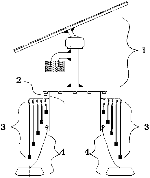
[0039] exist figure 1 Among them, the upper connection device of the electromechanical floating tank (2) has a light energy collection device (1), the upper part outside the side wall is connected to the compressed air output device (3), and the lower part outside the side wall is connected to the positioning device (4). Mobile automatic control floating tank aerator.

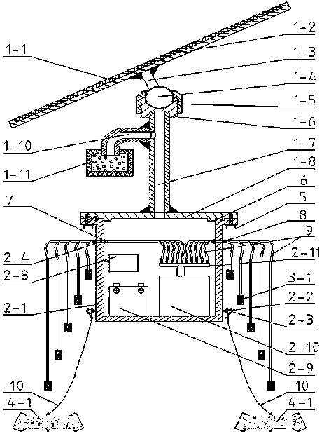
[0040] exist figure 2 Among them, the ventilation screw hole (2-4) of the floating tank (2-1) is equipped with a straight-through joint (7) and a check valve nozzle (8), the straight-through connector (7) is in the wall, and the check valve nozzle (8) outside the wall; battery (2-9), automatic controller (2-8), aeration pump (2-10), aeration pump (2-10) are installed in the floating cabin (2-1) There is a branching head (2-11), and the branching head (2-11) is connected ...


PUM


Abstract

A fully automatic optical energy oxygen-increasing machine is characterized in that usage is convenient; motion is flexible; the oxygen increasing machine can be installed at either position of a pond, and can fix an orientation of an optical energy cell panel; oxygen increasing requirements of different water layers can be solved; and a professional automatic controller makes an oxygen increasingpump more efficient in utilizing solar energy. The oxygen-increasing machine is mainly composed of an optical energy collection device, an electromechanical buoyancy chamber, compressed air output devices, and positioning devices. The optical energy collection device is composed of a photovoltaic cell, a supporting rack, a ball head connecting rod, a ball head, a steering nut, a steering screw seat, an air filter, a bend-way elbow, a through hole supporting pillar and a hatch cover; the electromechanical buoyancy chamber is composed of a buoyancy chamber, a storage battery, an automatic controller, the oxygen increasing pump, a tube splitting head, flexible pipes, straight-through joints and check valve air nozzles; each of the compressed air output devices is composed of flexible pipes and bubble stones; and each of the positioning devices is composed of connection cables and sinkers.

Description

technical field [0001] The invention relates to water body oxygenation equipment, in particular to an automatic control floating tank oxygenation machine driven by light energy. Background technique [0002] In aquaculture production, the oxygen content of the water body directly affects the quality and benefits of aquatic product farming. The usual aquaculture water body cannot meet the oxygen uptake needs of aquatic organisms. In order to solve this problem, most of the existing technologies use various augmentations Oxygenation equipment can increase oxygen in water bodies. At present, there are more advanced solar oxygenation equipment. Because the light energy of solar energy is free, it can save energy and cost, and it is convenient, environmentally friendly and energy-saving, etc., which is especially valued and rewarded by the national government. In recent years, there have been some technologies and equipment for solar oxygen enhancement, but because they are still...

Claims


Application Information

Patent Timeline
Patent Type & Authority Applications(China)
IPC IPC(8): A01K63/04F24S20/70H02J7/35H02S20/00
CPCA01K63/042H02J7/35H02S20/00Y02E10/50
Inventor 夏其中
Owner 苗国华
Why Eureka
Try Eureka