Exhaust after-treatment system

An exhaust duct and gas technology, applied in exhaust treatment, exhaust devices, separation methods, etc., can solve problems such as reducing machine fuel economy

Pending Publication Date: 2018-11-09
CATERPILLAR INC
View PDF8 Cites 6 Cited by
  • Summary
  • Abstract
  • Description
  • Claims
  • Application Information

AI Technical Summary

Problems solved by technology

High temperature regeneration usually requires what is called active regeneration, which requires the use o...

Method used


Image

  • Exhaust after-treatment system
  • Exhaust after-treatment system
  • Exhaust after-treatment system

Examples


Embodiment Construction

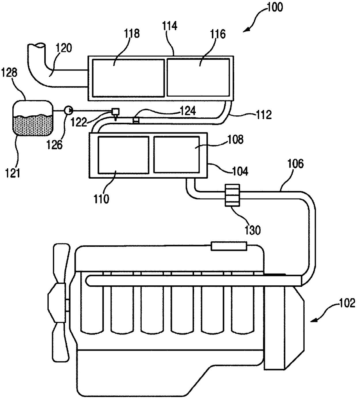
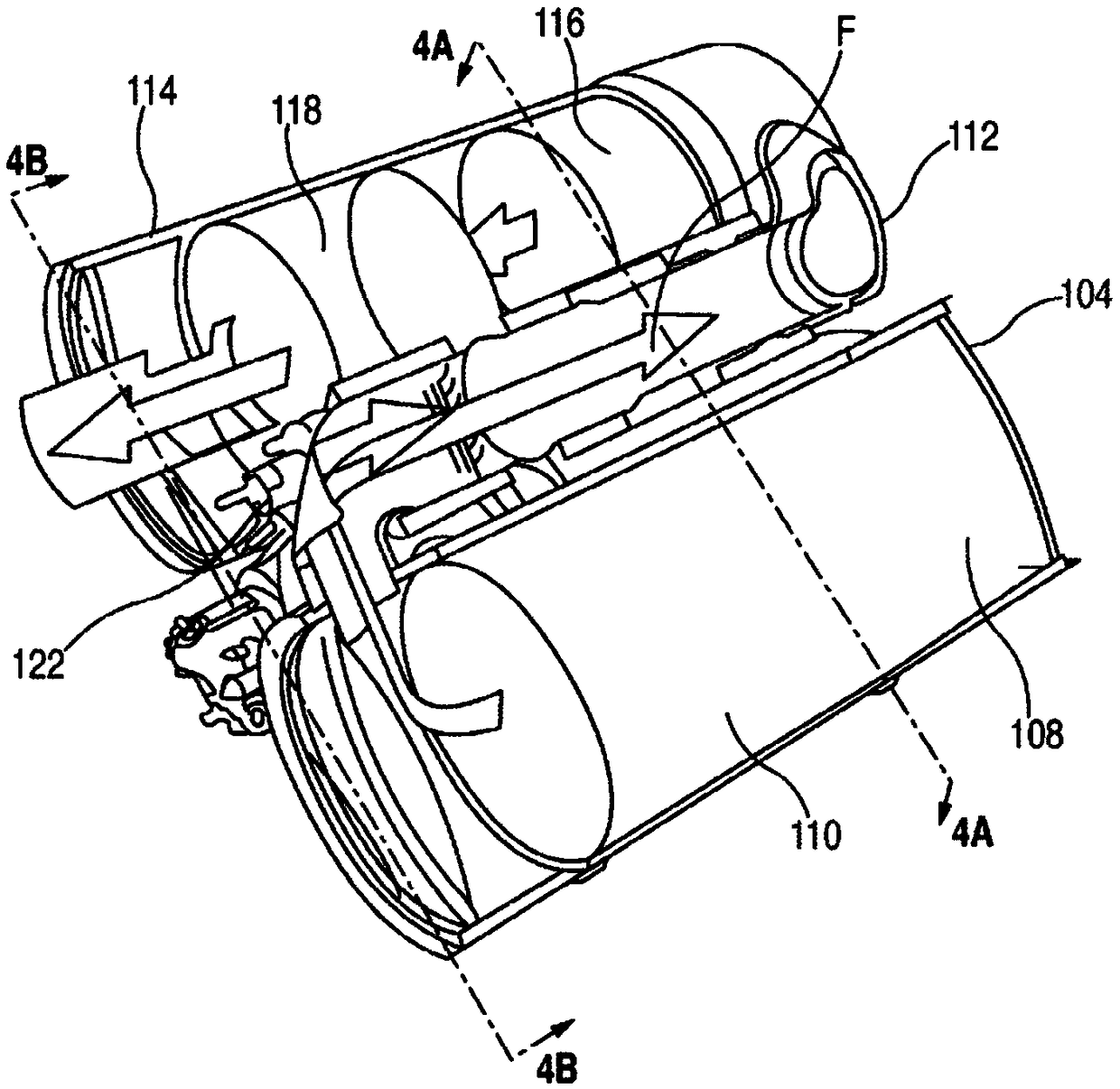
[0011] 1 and 2 are representations of an exhaust aftertreatment system 100 known in the art. In the illustrated embodiment, system 100 includes a first module 104 fluidly connected to an exhaust conduit 106 of engine 102 . During engine operation, the first module 104 is arranged to internally receive engine exhaust from the conduit 106 . The first module 104 contains a diesel oxidation catalyst (DOC) 108 arranged in series upstream of a diesel particulate filter (DPF) 110 , each of which has a relatively large frame. It should be noted that CDPF 110 is a coated DPF (CDPF). Exhaust gas provided by the engine 102 to the first module 104 first passes through the DOC 108 , then through the CDPF 110 , and then into the transfer conduit 112 .

[0012] A transfer conduit 112 fluidly interconnects the first module 104 with the second module 114 such that exhaust gases from the engine 102 may pass through the first module 104 and the second module 114 in series before being released...


PUM


Abstract

An after-treatment system (200) includes, in series along an exhaust gas flow direction through the after-treatment system (200): a diesel oxidation catalyst (108)), a diesel exhaust fluid (DEF) delivery device, a soot- reducing device and a selective catalytic reduction (SCR) catalyst.

Description

technical field [0001] The present disclosure relates generally to engine systems, and more particularly to exhaust aftertreatment systems and methods. Background technique [0002] One known method for reducing certain diesel engine exhaust constituents is the use of exhaust aftertreatment systems utilizing selective catalytic reduction (SCR) of nitrogen oxides. In a typical SCR system, urea or a urea-based aqueous solution is mixed with the exhaust gas. In some applications, the urea solution is sprayed directly into the exhaust passage through a special injector device. The injected urea solution, which is sometimes referred to as Diesel Exhaust Fluid (DEF), mixes with and decomposes the exhaust to provide ammonia (NH 3 ). Then, the ammonia reacts with the nitrogen oxides (NO x ) react to provide nitrogen (N 2 ) and water (H 2 O). [0003] In typical applications, especially for large engines, a high efficiency diesel particulate filter (DPF) is used in conjunction...

Claims


Application Information

Patent Timeline
IPC IPC(8): F01N3/10F01N3/20F01N3/023F01N3/035F01N13/00F01N3/021
CPCF01N3/106F01N3/021F01N3/0231F01N3/035F01N2340/00F01N2340/02F01N2570/18F01N2610/00F01N13/0097F01N13/009F01N3/103F01N3/2066Y02T10/12Y02A50/20B01D53/9418B01D53/9436B01D53/944B01D53/9468B01D53/9477B01D2255/9022B01D2255/904B01D2255/91F01N3/0222F01N3/206F01N2240/40F01N2330/48
Inventor A·C·罗德曼J·J·德里斯科尔B·巴莱亚W·J·罗贝尔
Owner CATERPILLAR INC
Why Eureka
Try Eureka