Optical fiber structures and methods for varying laser beam profile

A laser beam and optical fiber technology, applied in the field of laser systems, can solve the problems of damage, expensive and time-consuming fragile optical components of laser systems

Active Publication Date: 2018-11-09
TERADIODE
View PDF15 Cites 3 Cited by
  • Summary
  • Abstract
  • Description
  • Claims
  • Application Information

AI Technical Summary

Problems solved by technology

In order to make such changes to the BPP of a laser system, often the output optics or fiber must be swapped and/or realigned with other compone

Method used


Image

  • Optical fiber structures and methods for varying laser beam profile
  • Optical fiber structures and methods for varying laser beam profile
  • Optical fiber structures and methods for varying laser beam profile

Examples


Embodiment Construction

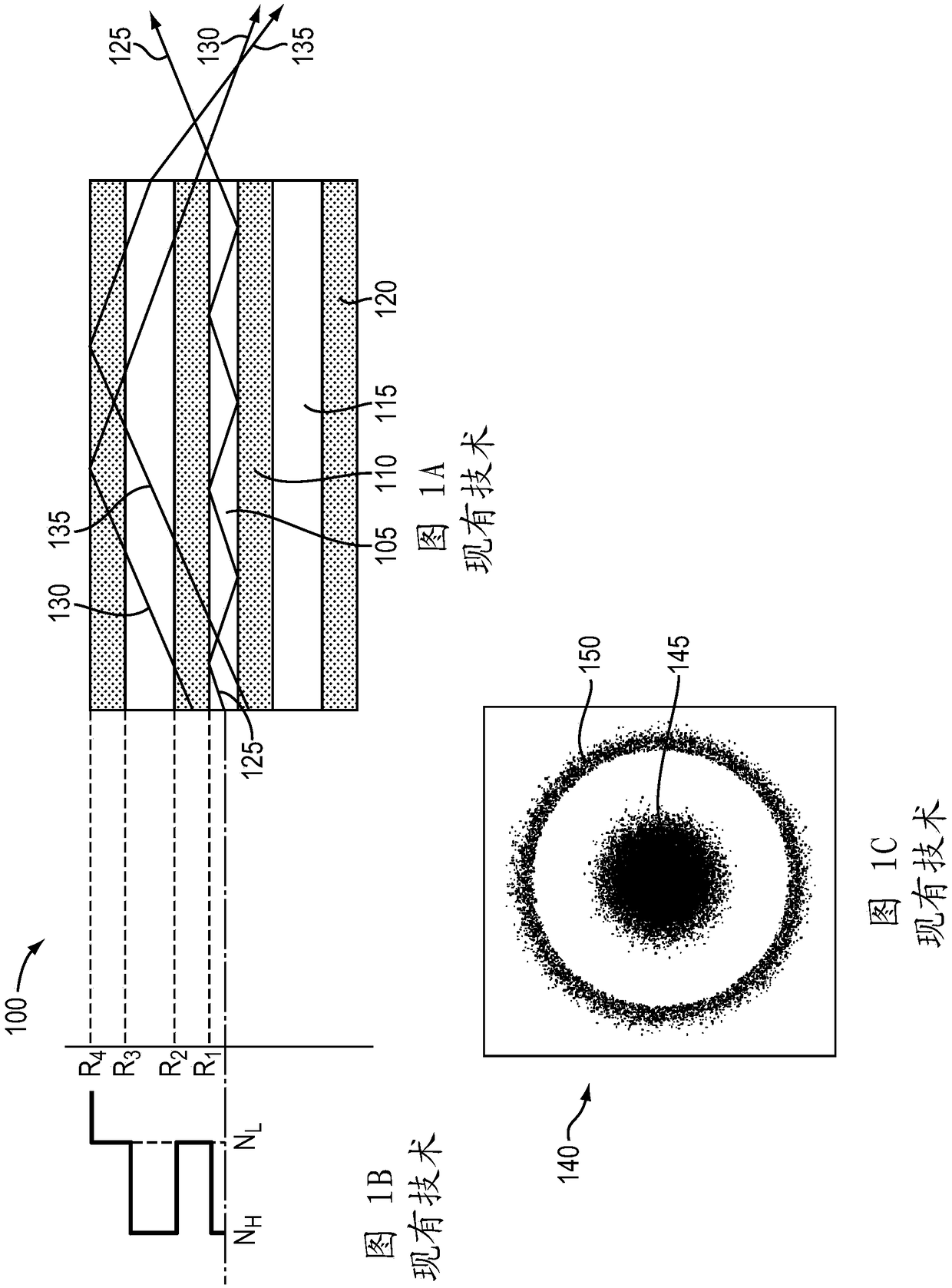
[0034] Figure 1A A conventional double clad fiber 100 is shown having a central core 105 , an inner cladding 110 , a ring core 115 and an outer cladding 120 . The radius of each layer (core or cladding) of fiber 100 is given by R 1 , R 2 , R 3 or R 4 means, such as Figure 1B shown. In a conventional double-clad fiber 100, the two cores 105, 115 typically have the same higher refractive index N H , and the two cladding layers 110, 120 generally have the same lower refractive index N L ,Such as Figure 1BAs shown, therefore, the two cores 105, 115 have the same NA: sqrt(N H 2 -N L 2 ).

[0035] Figure 1A The transmission of three representative rays in fiber 100 is also depicted. Light ray 125 is coupled into central core 105 , is confined by central core 105 , and exits central core 105 at the same angle as it entered central core 105 . Rays 130 and 135 are transmitted into inner cladding 110 , propagate throughout the fiber region, and are confined by outer c...


PUM


Abstract

In various embodiments, the beam parameter product and/or numerical aperture of a laser beam is adjusted utilizing a step-clad optical fiber having a central core, a first cladding, an annular core, and a second cladding.

Description

[0001] related application [0002] This application claims the benefit of and priority to U.S. Provisional Patent Application No. 62 / 318,959, filed April 6, 2016, the entire disclosure of which is incorporated herein by reference. technical field [0003] In various embodiments, the present invention relates to laser systems, particularly laser systems with controllable beam profiles (eg, variable beam parameter products). Background technique [0004] High power laser systems are used in many different applications such as welding, cutting, drilling and material processing. Such laser systems typically include a laser transmitter from which the laser light is coupled to an optical fiber (or simply "fiber"), and an optical system that focuses the laser light from the fiber onto the workpiece to be processed. Optical systems are generally designed to produce the highest quality laser beam, or equivalently, the beam with the lowest beam parameter product (BPP). BPP is the ...

Claims


Application Information

Patent Timeline
IPC IPC(8): G02B6/036
CPCH01S5/0071H01S5/143H01S5/4031H01S5/405H01S5/4062H01S5/4087H01S2301/20G02B6/4214G02B2006/12104G02B2006/12121G02B6/03644H01S5/005G02B6/32G02B6/02042G02B6/34G02B17/00
Inventor 周望龙F·维拉里尔-绍塞多P·塔耶巴提B·陈
Owner TERADIODE
Why Eureka
Try Eureka