Supercharge Your Innovation With Domain-Expert AI Agents!

Light source module unit for exposure and exposure device provided with the light source module unit

A light source module and light source technology, applied in the field of exposure light sources, can solve problems such as high power consumption, low efficiency, and low lifespan, and achieve the effects of reduced light source replacement costs, high-efficiency exposure technology, and low power consumption

Active Publication Date: 2021-04-27
赵南稙
View PDF4 Cites 0 Cited by
  • Summary
  • Abstract
  • Description
  • Claims
  • Application Information

AI Technical Summary

Problems solved by technology

[0003] Usually, the light sources for exposure used in the existing exposure process mainly use ultra-high pressure mercury lamps or halogen lamps, but the fact is that, as well known, the existing light sources for exposure as described above are exposed due to low life and high consumption. Not only the low efficiency caused by electricity and the efficiency of the exposure process caused by high costs, but also many problems in the environment
[0004] In particular, recently, when manufacturing thin film transistors (TFT, Thin Film Transistor) or manufacturing color filters (CF, Color Filter) in the display field similar to liquid crystal displays (LCD) or organic light emitting diodes (OLED), the market is demanding the use of exposure patterns. There is an urgent need for miniaturization technology to achieve ultra-high definition. However, due to the technical limitations of the miniaturization process of the exposure pattern using the existing exposure light source (Hg Lamp, mercury lamp), although it is a pity, the reality is that it cannot be realized as an exposure pattern. UHD, the core technology of miniaturization and display industry
[0005] In addition, due to the recent trend of miniaturization, increase in capacity, and high integration and high density of semiconductor elements, there is an increasing demand for miniaturization and high precision of exposure patterns. Existing light sources for exposure have limitations in meeting the current requirements for miniaturized patterns

Method used


Image

  • Light source module unit for exposure and exposure device provided with the light source module unit
  • Light source module unit for exposure and exposure device provided with the light source module unit
  • Light source module unit for exposure and exposure device provided with the light source module unit

Examples


Embodiment Construction

[0044] Hereinafter, the light source module head unit for exposure according to the present invention will be described in detail with reference to the accompanying drawings. The content described below and the accompanying drawings are merely descriptions based on preferred embodiments of the present invention, and do not limit the light source module unit for exposure of the present invention described in the claims.

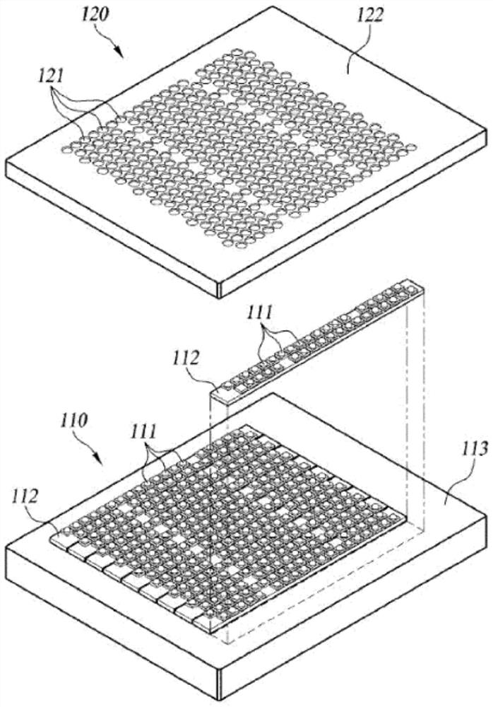
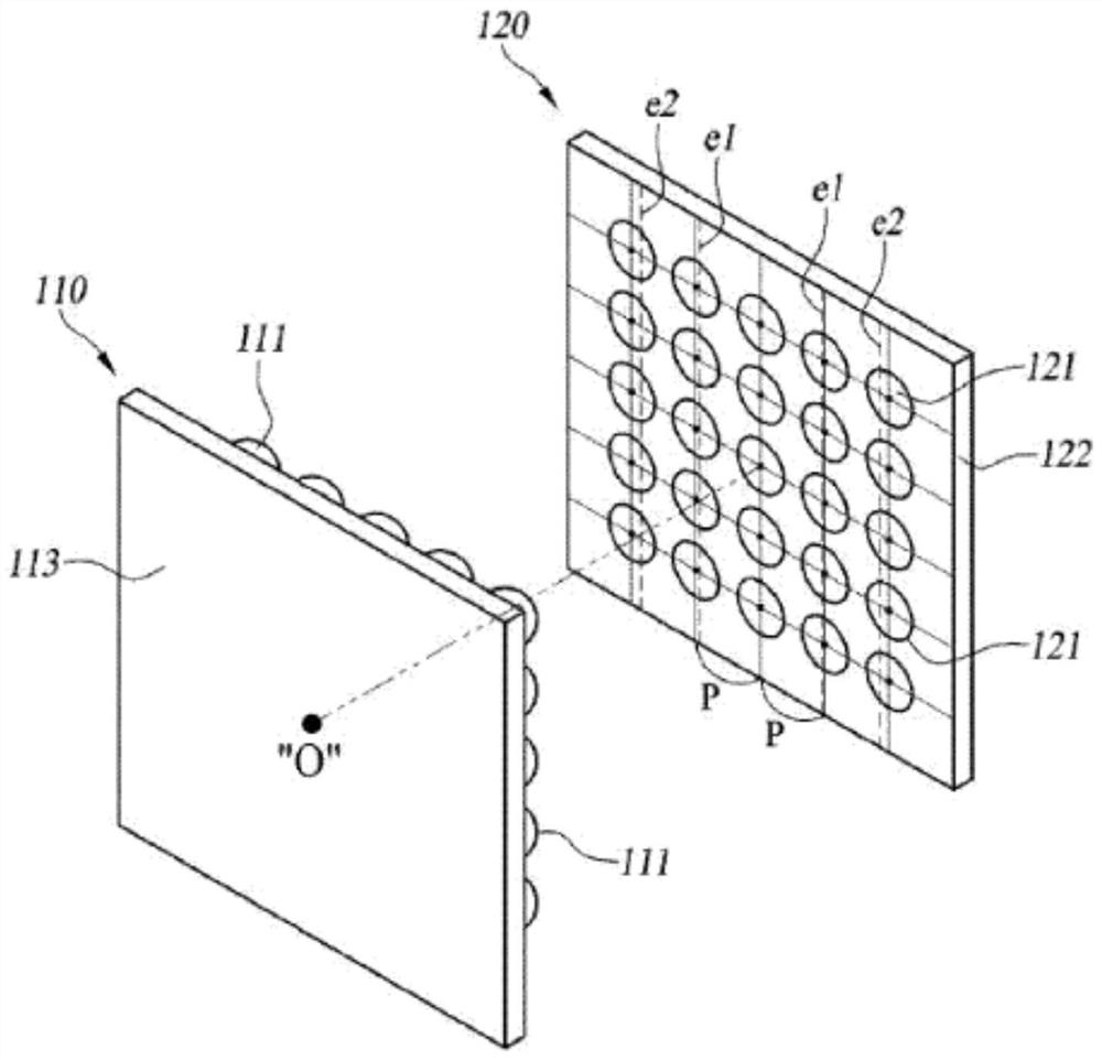
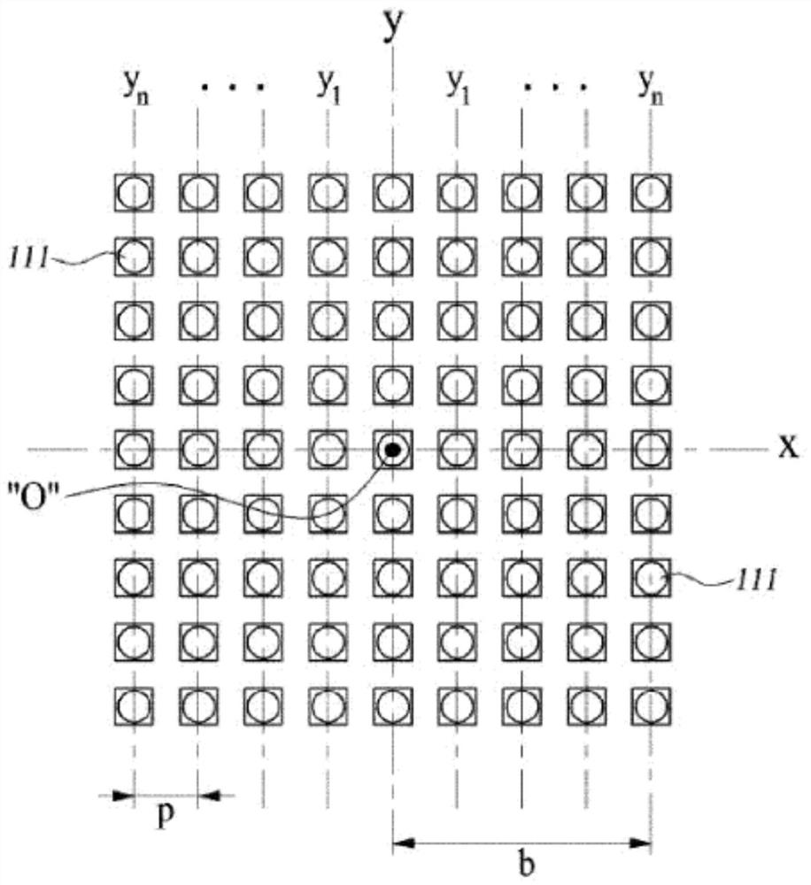
[0045] refer to figure 1 and figure 2 According to the exposure light source module unit 100 of the present invention, it includes: a light source panel 110, which is arranged as a plurality of unit ultraviolet light emitting elements (UV LEDs) 111 mounted on a circuit board 112 in a matrix array structure, and loaded on a support panel 113; an optical panel 120, which is formed in a form facing the light source panel 110, the lens panel 122 is arranged on the light emitting side of the unit ultraviolet light emitting element 111, and on the lens panel 122, ...


PUM


Abstract

The invention discloses a light source module unit for exposure. The light source module unit for exposure according to the present invention includes: a light source panel, which arranges a plurality of ultraviolet light emitting elements in an array structure; It is an array structure in a matrix form in a state in which the main optical axis passes through the arbitrary reference central axis side of the center of the ultraviolet light emitting element array from the positions corresponding to the unit light emitting elements respectively. The unit condenser lens has the following configuration: The surface is formed in any form selected from a flat surface, a concave surface with a curvature (R) within (‑) 0.15, and a convex surface with a curvature (R) within (+) 0.15, and the light exit surface is formed as a convex lens, The distance (C1) between the ultraviolet light-emitting element and the unit condenser lens is arranged so that it satisfies 0.15 with respect to the diameter (d) of the condenser lens.

Description

technical field [0001] The present invention relates to a light source for exposure, and in more detail to an ultraviolet light emitting element (UVLED) light source module unit for exposure, which is used in photolithography (Photolithography) to form fine circuit patterns on semiconductor wafers or image display panels. ) process, in particular, relates to an ultraviolet light emitting element (UV LED) light source module unit for exposure and an exposure device provided with the light source module unit, which is improved in the following form: for the ultraviolet light emitting element (UV LED) as a light source ) The optical arrangement structure and shape structure of the condensing lens can effectively improve the exposure performance and exposure efficiency by maximizing the light output power (power) and illumination distribution through the composition of the optimal combination of array modules. A light source module set-up in an existing exposure apparatus can be e...

Claims


Application Information

Patent Timeline
Patent Type & Authority Patents(China)
IPC IPC(8): G03F7/20F21K9/60F21V5/04F21V29/70F21V8/00
CPCF21V5/04G03F7/20F21V29/70F21K9/60
Inventor 赵南稙印致亿朴钟沅宋友莉丁海一
Owner 赵南稙
Features
  • R&D
  • Intellectual Property
  • Life Sciences
  • Materials
  • Tech Scout
  • Unparalleled Data Quality
  • Higher Quality Content
  • 60% Fewer Hallucinations
Learn More