
A low frequency pulse vibration generator

A vibration generator and low-frequency pulse technology, applied in the field of oscillators, can solve the problems of limited application occasions, narrow adjustment range of oscillation frequency, high ultrasonic oscillation frequency, etc., and achieve the effect of simple structure

Active Publication Date: 2020-02-04
山东润蒙应急救援装备有限公司
View PDF4 Cites 1 Cited by
  • Summary
  • Abstract
  • Description
  • Claims
  • Application Information

AI Technical Summary

Problems solved by technology

[0003] Affected by the ultrasonic frequency, the ultrasonic oscillation frequency is high and its oscillation frequency adjustment range is narrow, which limits its application

Method used


Image

  • A low frequency pulse vibration generator
  • A low frequency pulse vibration generator
  • A low frequency pulse vibration generator

Examples


Embodiment Construction

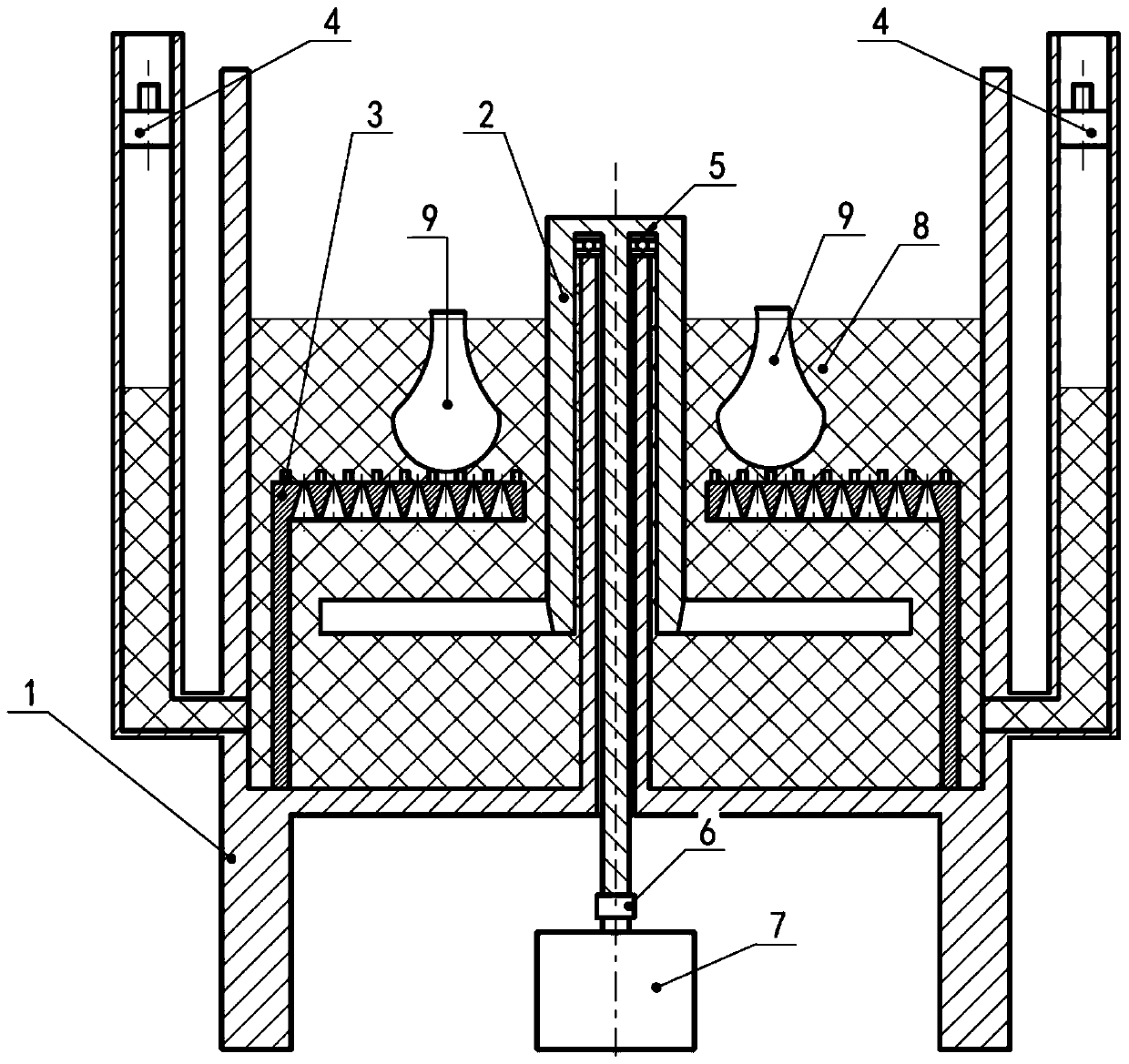
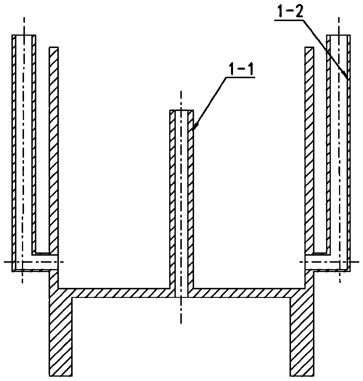
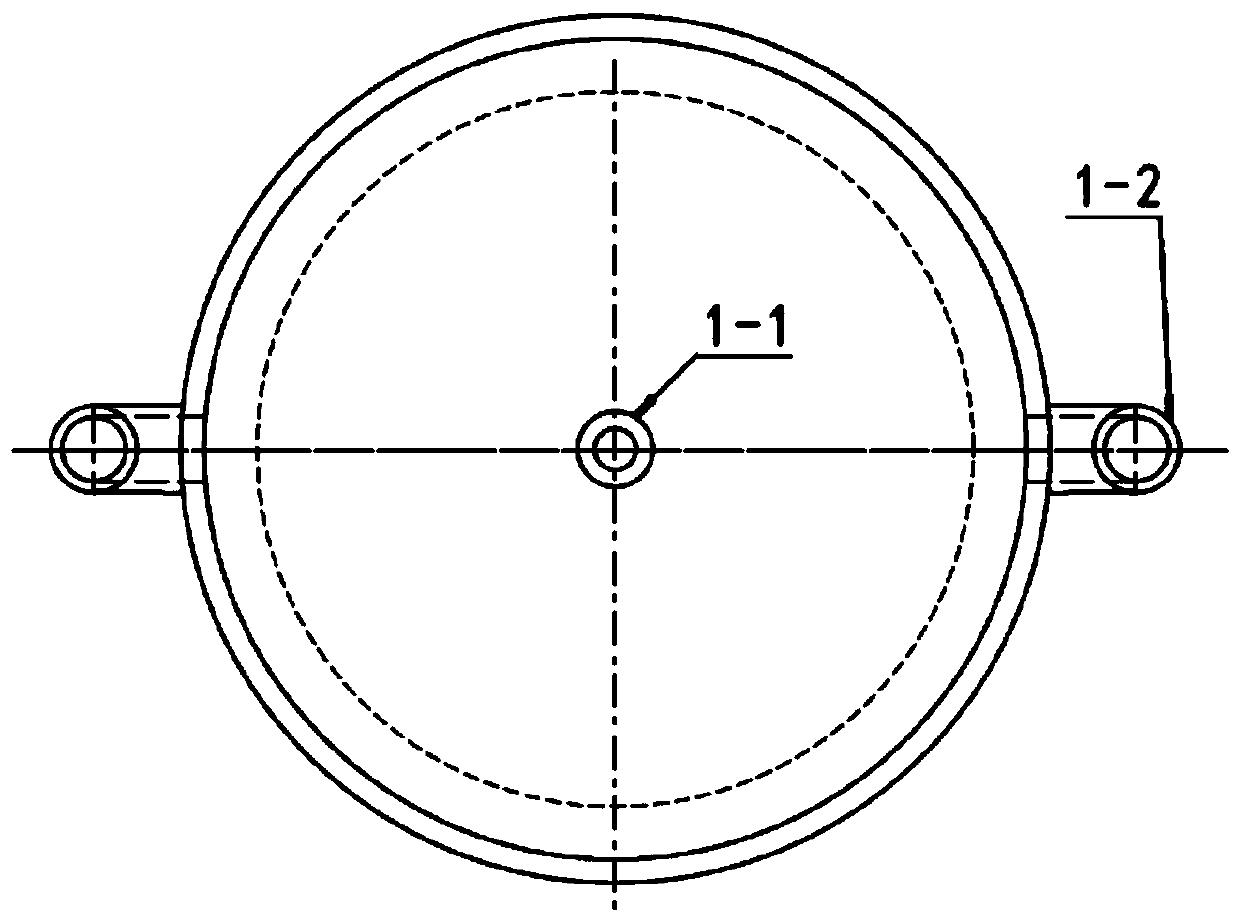
[0020] exist figure 1 , figure 2 and image 3 In the schematic diagram of the low-frequency pulse vibration generator shown, the bottom of the oscillator cavity 1 is connected to the supporting legs, the liquid 8 is filled in the oscillator cavity, and the gas booster chambers 1-2 are arranged on opposite sides of the oscillator cavity. The gas pressurization chamber is higher than the oscillator chamber and connected with it, and the gas pressurization chamber is equipped with a pressing block 4 to increase the pressure above the liquid in the pressurization chamber, and the propeller frame 1-1 is arranged in the oscillator chamber The center of the body, one end of which is connected to the oscillator cavity, and the other end is connected to the rotary paddle 2, the liquid level in the oscillator cavity is lower than the propeller frame, and the bubble destruction frame 3 is located on the outside of the oscillator cavity;

[0021] Such as Figure 4 , Figure 5 and F...


PUM


Abstract

The invention discloses a low-frequency pulse vibration generator. The low-frequency pulse vibration generator comprises an oscillator cavity, gas supercharging cavities, a propeller frame, a propeller, a bubble disappearing frame and a rotating motor, wherein the bottom of the oscillator cavity is connected with support legs; the oscillator cavity is filled with liquid; the gas supercharging cavities are arranged on two opposite sides of the oscillator cavity; the gas supercharging cavities are higher than the oscillator cavity and connected with the cavity; pressing blocks are arranged in the gas supercharging cavities for increasing the pressure above the liquid in the supercharging cavities; the cylindrical propeller frame is arranged in the center of the oscillator cavity, one end isconnected with the oscillator cavity, and the other end is connected with the propeller; the liquid level in the oscillator cavity is lower than that of the propeller frame; and the bubble disappearing frame is arranged on the outer side in the oscillator cavity. The low-frequency pulse vibration generator is simple in structure, can generate low-frequency oscillation, and can adjust the oscillation frequency in wide range.

Description

technical field [0001] The invention belongs to the field of industrial equipment, in particular to an oscillator. Background technique [0002] Oscillators are involved in many fields of industry and are mainly used in cleaning, stirring and material preparation processes. The existing oscillator mainly converts electromagnetic oscillation into ultrasonic oscillation through a transducer. The ultrasonic wave has good directionality, strong penetrating ability, easy to obtain relatively concentrated sound energy, and has a relatively long propagation distance in liquid. Due to the radiation of ultrasonic waves, the microbubbles in the liquid in the tank can keep vibrating under the action of sound waves to achieve the desired purpose. [0003] Influenced by the frequency of the ultrasonic wave, the oscillation frequency of the ultrasonic wave is high and the adjustment range of the oscillation frequency is narrow, which limits its application. Contents of the invention ...

Claims


Application Information

Patent Timeline
Patent Type & Authority Patents(China)
IPC IPC(8): B06B1/18B06B3/02
CPCB06B1/18B06B3/02
Inventor 李雪爱曲相燕王海燕
Owner 山东润蒙应急救援装备有限公司
Learn More