Cooling device for glass base plate rack forming die

A technology for forming molds and cooling devices, applied in the field of glass substrate racks, can solve the problems of reduced reliability and life, poor control accuracy of cooling devices, and rising mold costs, and achieves enhanced heat exchange efficiency, uniform cooling effect, and improved cooling. The effect of efficiency

Inactive Publication Date: 2018-11-13
芜湖良匠机械制造有限公司
View PDF6 Cites 2 Cited by
  • Summary
  • Abstract
  • Description
  • Claims
  • Application Information

AI Technical Summary

Problems solved by technology

[0006] (1) The cooling pipes in the existing glass substrate rack forming molds are mainly arranged in two types: straight-through type and mixed-arrangement type. The design of the water channel is flexible, and the number, position, and shape of the water channel can be changed arbitrarily. This cooling method can achieve high cooling efficiency while ensuring the forming accuracy and strength, and speed up the production cycle. However, for large-scale glass substrate rack molding molds, The machining of slender pipes in molds has always been a challenge;
[0007] (2) The cooling device used in the existing rack forming mold lacks a valve pipeline conversion device on the internal cooling pipe, so that the flow control of the cooling water is poor, and it is easy to cause the internal water pressure and air pressure of the cooling device to be controlled. The accuracy is poor, and the inner wall of the cooling water pipe is damaged;
[0008] (3) The existing large-scale glass substrate frame molding mold adopts the electric heating RHCM process based on

Method used


Image

  • Cooling device for glass base plate rack forming die
  • Cooling device for glass base plate rack forming die
  • Cooling device for glass base plate rack forming die

Examples


Example Embodiment

[0037] The technical solutions in the embodiments of the present invention will be clearly and completely described below in conjunction with the accompanying drawings in the embodiments of the present invention. Obviously, the described embodiments are only a part of the embodiments of the present invention, rather than all the embodiments. Based on the embodiments of the present invention, all other embodiments obtained by those of ordinary skill in the art without creative work shall fall within the protection scope of the present invention.

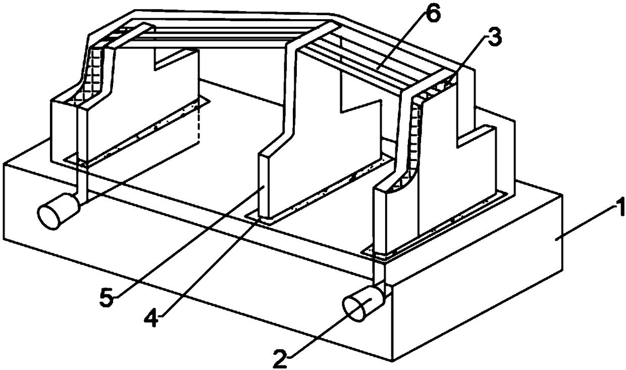
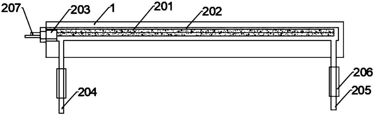
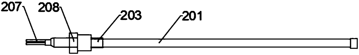
[0038] Such as Figure 1 to Figure 7 As shown, the present invention provides a cooling device for a glass substrate frame forming mold, which includes a distribution plate 1, a rapid thermal cycle device 2 and a pneumatic angle seat valve 3. The distribution plate 1 is provided with a rapid thermal cycle Device 2, the two ends of the rapid thermal cycle device 2 are connected with a hollow punch 5 through water inlet and outlet pipes, a...


PUM


Abstract

The invention discloses a cooling device for a glass base plate rack forming die. The cooling device comprises a flow distributing plate, a rapid heat circulation device and pneumatic angle seat valves. The rapid heat circulation device is arranged in the flow distributing plate. The two ends of the rapid heat circulation device are connected with hollow male dies through a water inlet and outletpipeline. A plurality of cooling water runners are arranged at the upper portions of the hollow male dies in parallel. The right ends of the cooling water runners are fixedly provided with the pneumatic angle seat valves. The bottoms of the pneumatic angle seat valves are fixedly arranged on the outer walls of the hollow male dies through fine adjustment screws. The opposite drill manner is adopted, drilling is conducted from the two ends to the middle to arrange the cooling water runners in the die, die material and plate material cooling is achieved through heat exchange between the coolingwater runners and the die, the cooling water runners are distributed in the male dies and female dies in a staggered manner, temperature compensation can be provided between the cooling water runners,the male dies and the female dies, the cooling effect is more uniform, the cooling water flow is effectively increased, accordingly, the heat exchange efficiency between the cooling water and the dieis enhanced, and the system stability is improved.

Description

technical field [0001] The invention relates to the field of glass substrate frames, in particular to a cooling device for forming molds for glass substrate frames. Background technique [0002] In the glass substrate frame injection molding, the glass substrate frame molding mold is not only the forming equipment for the glass substrate frame melt, but also plays the role of a heat exchanger. The mold temperature adjustment system directly affects the quality and production efficiency of the product. Due to the different performance and forming process requirements of various glass substrate racks, the requirements for mold temperature are also different. Design is an important part of injection mold design, and the existing cooling devices for glass substrate frame molding molds still have the following shortcomings: [0003] For example, the application number is 201710332099.9, and the patent name is an invention patent of a mobile cooling device for marine cable extrus...

Claims


Application Information

Patent Timeline
IPC IPC(8): B29C45/73B29C45/26B29C45/78
CPCB29C45/2602B29C45/7312B29C45/78B29C2945/76531
Inventor 范和峰
Owner 芜湖良匠机械制造有限公司
Why Eureka
Try Eureka