A kind of steel pipe pile with oblique outrigger and its construction method

A technology of steel pipe piles and steel pipes, applied in sheet pile walls, foundation structure engineering, construction, etc., can solve problems such as low bearing capacity and smooth side walls, and achieve the effects of reduced friction, reduced consumption, and low earth pressure

Active Publication Date: 2020-12-22
HEFEI WISDOM DRAGON MACHINERY DESIGN CO LTD
View PDF1 Cites 0 Cited by
  • Summary
  • Abstract
  • Description
  • Claims
  • Application Information

AI Technical Summary

Problems solved by technology

[0006] The purpose of the present invention is to provide a steel pipe pile with obliquely extending arms, which can solve the technical problems of smooth side walls and low bearing capacity of existing steel pipe piles, so that the side friction resistance and bearing capacity are greatly improved, and can be applied to Strengthening of building foundations

Method used


Image

  • A kind of steel pipe pile with oblique outrigger and its construction method
  • A kind of steel pipe pile with oblique outrigger and its construction method
  • A kind of steel pipe pile with oblique outrigger and its construction method

Examples


Embodiment 1

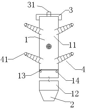
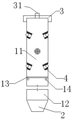
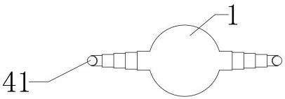
[0041] Such as Figure 1-3 Shown: a steel pipe pile with an oblique outrigger, including a pile body 1 and a pile tip 2, the pile body 1 is a steel pipe structure, the pile tip 2 is a circular platform structure with an open bottom, the pile The body 1 and the pile point 2 are integrally formed, and a partition 13 is arranged in the pile body 1, and the partition 13 separates the inner cavity of the steel pipe of the pile body into an upper cavity 11 and a lower cavity 12 which are independent of each other; During the process, the soil plug that can enter the lower cavity through the pile tip opening can fill the lower cavity (most of the cavity of the pile body), reducing the amount of cement slurry;

[0042] The pile body of the upper cavity 11 is connected with an outrigger 4 that can protrude to the outside of the pile body 1 and insert into the soil; after the outrigger is inserted into the soil, the side friction resistance and bearing capacity of the steel pipe pile ar...

Embodiment 2

[0056] Embodiment 2 is the construction method of Embodiment 1, and the specific method is: a construction method of a steel pipe pile with an oblique outrigger, and its specific steps are as follows:

[0057] 1) Provide a steel pipe pile with an oblique outrigger as described in Embodiment 1;

[0058] 2) Set out the line to determine the pile position, use the suspension ring to suspend the steel pipe pile with obliquely extending arms directly above the pile position, and align the pile tip with the middle position of the pile position;

[0059] 3) Start the pile driver, and slowly insert the steel pipe pile with oblique outrigger into the foundation;

[0060] 4) When the pile body reaches the predetermined depth, cover the pile cover 3, use a high-pressure air pump to inject high-pressure gas into the upper cavity through the high-pressure inflation hole 31 on the pile cover 3, and stabilize the pressure for 5 to 8 minutes to ensure that the The outrigger 4 is fully stretc...


PUM


Abstract

The invention relates to a steel pipe pile with an inclined semi-girder and a construction method of the steel pipe pile. The steel pipe pile comprises a pile body and a pile point. The pile body is of a steel pipe structure, and the pile point is of a round table structure with an opening in the bottom. The pile body and the pile point are integrally formed. A separation plate is arranged in thepile body, and divides a pile body steel pipe inner cavity into an upper cavity and a lower cavity which are independent. The position, in the upper cavity, of the pile body is connected with the semi-girder capable of stretching out of the pile body and being inserted into soil, and the semi-girder is of a hollow structure with a sealed end and an open end. The upper cavity communicates with thehollow structure through an opening, and the semi-girder is inclined relative to the pile body. The side friction resistance and bearing capacity of the steel pipe pile are greatly improved, and the steel pipe pile is suitable for reinforcing a building foundation.

Description

technical field [0001] The invention relates to the technical field of steel piles, in particular to a steel pipe pile with an oblique outrigger and a construction method thereof. Background technique [0002] Engineering piles are divided into concrete piles, steel piles and composite material piles according to the pile material; [0003] Steel pipe pile is a kind of steel pile, which has the advantages of light weight and high bearing capacity. At present, it is widely used in marine engineering. However, the side wall of the steel pipe pile is smooth and the friction coefficient of the pile body is low. In view of this, the steel pipe pile is rarely used to strengthen the building foundation. [0004] In response to the above defects, the Chinese patent (publication number: CN106869106A) proposed a method for reinforcing the foundation with welded flank-type steel pipe piles. When the length of the ordinary steel pipe pile reaches two-thirds of the design pile length, u...

Claims


Application Information

Patent Timeline
Patent Type & Authority Patents(China)
IPC IPC(8): E02D5/48E02D5/50E02D5/62
CPCE02D5/48E02D5/50E02D5/62
Inventor 胡振华王颖肖洪天李大勇张宪堂张雨坤李朋
Owner HEFEI WISDOM DRAGON MACHINERY DESIGN CO LTD
Why Eureka
Try Eureka