Super-resolution optical microscopic imaging system and adjusting method thereof

An optical microscopy and imaging system technology, applied in the field of super-resolution imaging, can solve the problems of poor multi-wavelength beam shaping effect, poor spot shaping effect of solid beam and loss beam, and poor beam intensity distribution shaping effect, etc. Achieve the effect of improving imaging resolution, optimizing implementation, and improving resolution

Inactive Publication Date: 2018-11-13
SHANGHAI UNIV
View PDF0 Cites 9 Cited by
  • Summary
  • Abstract
  • Description
  • Claims
  • Application Information

AI Technical Summary

Problems solved by technology

[0004] In view of the shortcomings of the prior art described above, the purpose of the present invention is to provide a super-resolution optical microscopic imaging system and its adjustment method, which is used to solve the problem of beam intensity distribution of the multi-beam super-resolution microscopic imaging system in the prior art. Poor shaping effect, including poor shaping effect of solid beam and lost beam spot; and poor shaping effect of multi-wavelength beam coincidence, etc.

Method used


Image

  • Super-resolution optical microscopic imaging system and adjusting method thereof
  • Super-resolution optical microscopic imaging system and adjusting method thereof
  • Super-resolution optical microscopic imaging system and adjusting method thereof

Examples


Embodiment 1

[0056] see Figure 1 to Figure 7 . It should be noted that the diagrams provided in this embodiment are only schematically illustrating the basic idea of ​​the present invention, and only the components related to the present invention are shown in the diagrams rather than the number, shape and shape of the components in actual implementation. Dimensional drawing, the type, quantity and proportion of each component can be changed arbitrarily during actual implementation, and the component layout type may also be more complicated.

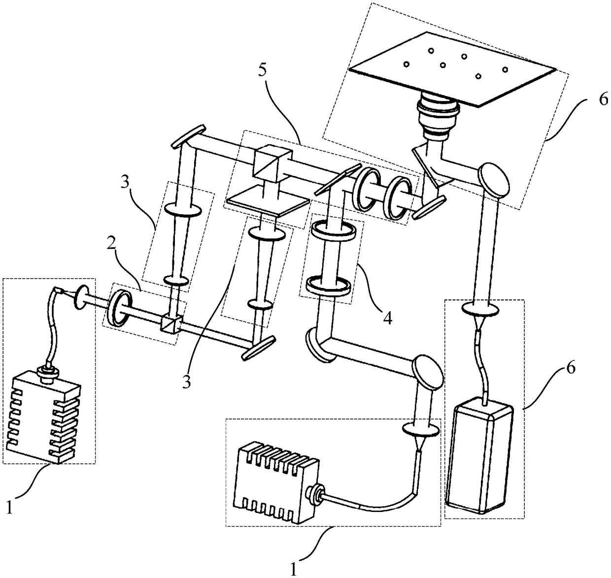
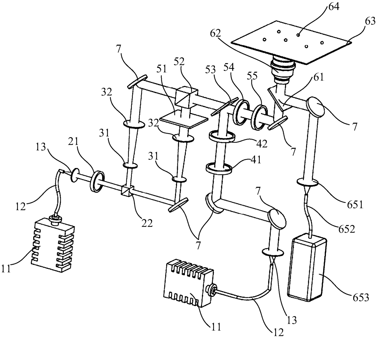
[0057] Such as figure 1 and figure 2 As shown, the present invention provides a super-resolution optical microscopic imaging system, the super-resolution optical microscopic imaging system includes: two laser light source shaping modules 1, a beam splitting module 2, two beam expanding modules 3, a first solid Beam adjustment module 4, a hollow beam modulation and beam coincidence adjustment module 5, a scanning imaging and detection module 6; ...

Embodiment 2

[0076] This embodiment is an adjustment method for the super-resolution optical microscopy imaging system proposed based on the first embodiment, and the adjustment step includes:

[0077] 1) In the laser light source shaping module 1, the optical fiber 12 and the collimating lens 13 respectively shape and collimate the light spots of the first laser beam and the second laser beam;

[0078] 2) In the scanning imaging and detection module 6, the objective lens 62 focuses the coincident light and irradiates it onto the gold nanoparticles 64, and is emitted to the The imaging device completes the real-time imaging process;

[0079] 3) According to the real-time imaging effect, adjust the hollow beam modulation and beam coincidence adjustment module 6 to complete the shaping adjustment of the coincidence light and the coincidence degree adjustment of the coincidence light.

[0080] As an example, the diameter of the gold nanoparticles 64 is between 70 nm˜90 nm.

[0081] This emb...


PUM

PropertyMeasurementUnit
diameteraaaaaaaaaa
widthaaaaaaaaaa

Abstract

The invention relates to a super-resolution optical microscopic imaging system and an adjusting method thereof. The super-resolution optical microscopic imaging system and the adjusting method thereofhave the advantages that the visual light intensity distribution of laser beams can be acquired by the scanning process of a three-dimensional nano translation platform and can be observed in real time; by using the hollow light beam to eliminate the sidelobe of the second solid light beam and increasing the first solid light beam to enhance the central light intensity of a light spot, the resolution of the imaging system is increased effectively; gold nano particles are used to adjust the light spot shape and intensity distribution of multiple light beams including the hollow light beam, thefirst solid light beam and the second solid light beam, the coincidence adjusting of the multiple light beams is completed by adjusting the divergence and incident angles of the light beams, and certain guidance and experimental significance to the further optimization of an STED system, the achievement of a multi-light-beam super-resolution system and the increasing of imaging resolution is achieved.

Description

technical field [0001] The invention relates to the technical field of super-resolution imaging, in particular to a multi-beam super-resolution microscopic imaging system and an adjustment method thereof. Background technique [0002] Optical microscopy has been widely used in biomedicine and cell biology because of its advantages of real-time, dynamic observation and less damage to samples. However, due to the existence of optical "diffraction limit", its imaging resolution is limited. At about 200nm, it greatly hinders its further development, such as some organelles, ribosomes, mitochondria, etc. in cells, and it is impossible to use optical microscopy to observe the fine structure. So Stefan W.Hell and Jan Wichman proposed the stimulated emission depletion microscopy (STED) technology based on confocal microscopy in 1994, and completed the experiment for the first time in 1999 by Hell and Thomas Klar According to the verification on the Internet, this technology uses th...

Claims


Application Information

Patent Timeline
Patent Type & Authority Applications(China)
IPC IPC(8): G02B21/00G01N21/84
CPCG02B21/0004G01N21/84G02B21/0032G02B21/0068G02B21/0076G02B21/008
Inventor 张力王中阳张金仓
Owner SHANGHAI UNIV
Why Eureka
Try Eureka