
Disk type bearingless induction motor

An asynchronous motor, bearingless technology, applied in asynchronous induction motors, electric components, electromechanical devices, etc., can solve the problems of large amount of calculation, high critical speed, complex decoupling control, etc., and achieve high suspension force density and torque density. big effect

Active Publication Date: 2018-11-13
HUAIYIN INSTITUTE OF TECHNOLOGY
View PDF2 Cites 0 Cited by
  • Summary
  • Abstract
  • Description
  • Claims
  • Application Information

AI Technical Summary

Problems solved by technology

On the one hand, the magnetic field of the torque winding interacts with the magnetic field of the levitation winding to generate radial levitation force; on the other hand, the magnetic field of the torque winding interacts with the rotating magnetic field of the rotor to generate torque. Therefore, the relationship between torque control and displacement control There is strong coupling, the control is complicated, it is difficult to establish an accurate mathematical model, and the control accuracy is low
In addition, in addition to the fact that the magnetic field of the torque winding will induce the rotor rotating magnetic field with the same number of pole pairs as the magnetic field of the torque winding in the rotor bar, the magnetic field of the suspension winding will also induce the same number of pole pairs of the magnetic field of the suspension winding in the rotor bar. The same rotor rotating magnetic field, the rotating magnetic field has a weakening effect on the levitation force, and will increase the complexity of torque control and displacement control, especially when it is running with load, and it will cause system instability in severe cases. suspension failure
Some scholars have proposed a bearingless asynchronous motor structure with a phase-separated rotor bar structure, but the number of pole pairs between the suspension winding and the torque winding of the motor still needs to satisfy P B = P M The relationship between ±1, the torque winding magnetic field must not only generate torque with the rotor magnetic field, but also generate levitation force with the levitation winding magnetic field. Promotion of its industrial application
[0004] To realize the stable suspension of the rotor with five degrees of freedom, it is necessary to have an axial magnetic bearing + a radial two-degree-of-freedom magnetic bearing + a two-degree-of-freedom bearingless asynchronous motor, or an axial magnetic bearing + two two-degree-of-freedom bearingless asynchronous motors Motor, or a two-degree-of-freedom bearingless asynchronous motor + a three-degree-of-freedom magnetic bearing to form a five-degree-of-freedom suspension drive system. In these three structures, an axial suspension control unit is inevitably required, resulting in a five-degree-of-freedom bearingless Asynchronous motor system has long axial length and high critical speed, it is difficult to achieve higher power and higher speed rotation, and it is bulky and expensive

Method used


Image

  • Disk type bearingless induction motor
  • Disk type bearingless induction motor
  • Disk type bearingless induction motor

Examples


Embodiment Construction

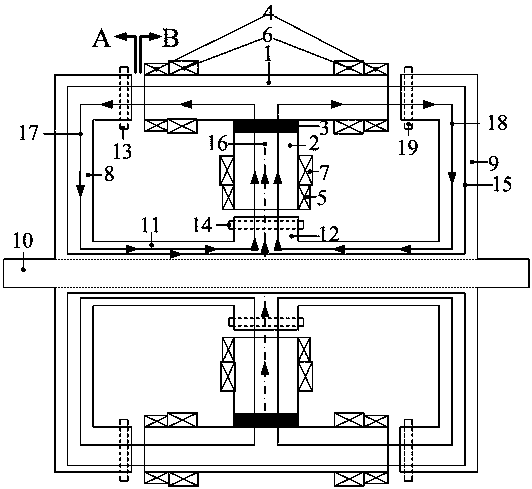
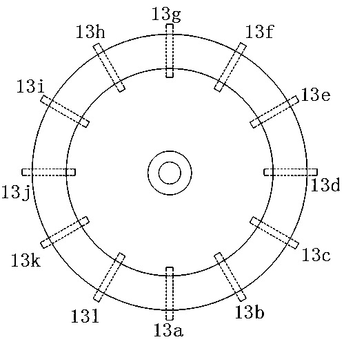
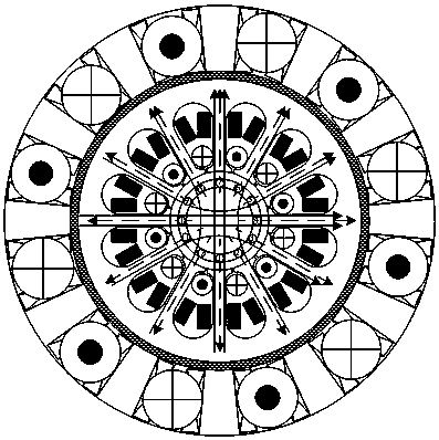
[0017] Such as Figure 1~3 A disc-type bearingless asynchronous motor is shown, taking the number of slots of the axial stator and rotor and the number of radial stator and rotor slots equal to 12 as an example; it includes a stator and a double-disc rotor, and the stator includes coaxial motors from outside to inside Connected axial stator core 1, permanent magnet ring 3, and radial stator core 2; both sides of the axial stator core 1 and the inner side of the radial stator core 2 are respectively provided with axial stator core slots and radial stator core slots. The slots of the axial stator core are provided with axial suspension windings 6 and axial torque windings 4 with different numbers of pole pairs in the axially outward direction, and the radial stator core slots are sequentially arranged radially outwardly. There are radial torque windings 5 ​​and radial suspension windings 7 with unequal numbers of pole pairs. The axial suspension windings 6 and radial suspension ...


PUM


Abstract

The invention discloses a disk type bearingless induction motor. The motor comprises a stator and a double-disk type rotor, wherein the stator comprises an axial stator core, a permanent magnet ring and a radial stator core; axial stator core grooves and radial stator core grooves are formed in two sides of the axial stator core and the inner side of the radial stator core, axial suspension windings and axial torque windings are arranged in the axial stator core grooves, and radial torque windings and radial suspension windings are arranged in the radial stator core grooves; the double-disk type rotor consists of an axial rotor core penetrating through the stator, disk type rotors coaxially connected to two ends of the axial rotor core and a radial rotor core connected to the middle of theaxial rotor core, the axial rotor core is coaxially connected with a rotating shaft extending out of the outer ends of the disk type rotors, axial rotor grooves are formed in inner ends of the disk type rotors, axial rotor conducting bars are arranged in the axial rotor grooves, and radial rotor conducting bars are arranged on the radial rotor cores.

Description

technical field [0001] The invention relates to the technical field of motor manufacturing, in particular to a disc-type bearingless asynchronous motor capable of realizing stable suspension of a rotor with three degrees of freedom and generating rotational torque in both the axial and radial directions. Background technique [0002] Bearingless asynchronous motors have no friction, no wear, no lubrication and no seals, and are easy to achieve higher speed and higher power operation. They have broad applications in aerospace, turbomolecular pumps, flywheel energy storage, sealed pumps, high-speed electric spindles, etc. prospect. [0003] At present, the bearingless asynchronous motor is by superimposing an additional set of suspension windings on the torque winding of the stator slot of the traditional asynchronous motor, and the two sets of windings are respectively powered by a three-phase AC power supply with the same frequency to generate the rotating suspension winding...

Claims


Application Information

Patent Timeline
IPC IPC(8): H02K17/30H02K17/18H02K1/17H02K1/22H02K3/28H02K11/21
CPCH02K1/17H02K1/22H02K3/28H02K11/21H02K17/30H02K2213/03H02K2201/12H02K2201/18H02K17/18
Inventor 张涛刘欣凤王业琴倪伟桑英军夏鑫丁卫红
Owner HUAIYIN INSTITUTE OF TECHNOLOGY
Learn More