A vision-guided mirror milling top support device for thin-walled parts

A technology for visual guidance and thin-walled parts, which can be used in positioning devices, metal processing machinery parts, manufacturing tools, etc., and can solve the problems of poor follow-up performance of support technology

Active Publication Date: 2021-01-05
NORTHWESTERN POLYTECHNICAL UNIV
View PDF1 Cites 0 Cited by
  • Summary
  • Abstract
  • Description
  • Claims
  • Application Information

AI Technical Summary

Problems solved by technology

[0004] In order to avoid the shortcomings of the existing technology and overcome the defect of poor follow-up performance of the supporting technology of mirror milling processing equipment, the present invention proposes a visually guided mirror milling supporting device for thin-walled parts

Method used


Image

  • A vision-guided mirror milling top support device for thin-walled parts
  • A vision-guided mirror milling top support device for thin-walled parts
  • A vision-guided mirror milling top support device for thin-walled parts

Examples


Embodiment Construction

[0031] This embodiment is a vision-guided mirror milling and supporting device for thin-walled parts.

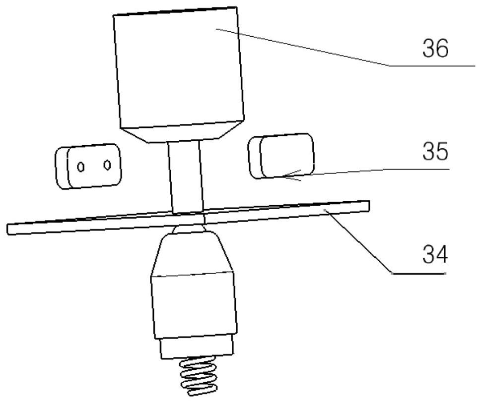
[0032] First, install two binocular vision cameras on one side of the processing head, so that the binocular cameras can see any pose of the processing head in real time. The visual part adopts two binocular vision cameras 35, and the binocular vision cameras are placed on one side of the processing head 36 of the mirror milling machine. The feature picture of the processing head is taken before processing and stored in the computer. When the processing head is processing the workpiece 34, the binocular camera will capture its pose in real time, and apply the feature matching technology based on the GMS algorithm to perform feature matching on each image and the image stored in the computer before, and use RPNP technology to calculate in real time after the matching is completed Output the pose of the processing head relative to the camera. Determine the pose transformatio...


PUM


Abstract

The invention discloses a visual-guided thin-walled workpiece mirror image milling jacking-supporting device which is composed of a jacking-supporting device visual part and a mechanical arm movementpart. The jacking-supporting device visual part adopts two binocular vision cameras to watch the arbitrary posture of a machining head in real time. The binocular vision cameras are placed on one sideof the mirror image milling machine tool machining head. The feature picture of the machining head is shot before machining and stored in a computer; when a workpiece is machined, the binocular cameras shoot the posture of the workpiece in real time, and all pictures and the picture stored into the computer previously are subjected to feature matching by applying a feature matching technology based on the GMS algorithm; the posture conversion relationship between the camera coordinate system and the mechanical arm coordinate system is determined; when the tail end of the machining head moves,a mechanical arm tail end actuator moves in real time along with the machining head in a mirror image synchronous mode; and servo motors of all joints of a mechanical arm are controlled through the computer to achieve waist rotation, shoulder rotation, elbow rotation and wrist rotation, and movement of a tail end jacking-supporting part is achieved.

Description

technical field [0001] The invention relates to the technical field of aerospace manufacturing, in particular to a vision-guided mirror milling top support device for thin-walled parts. Background technique [0002] There are many large thin-walled parts on aerospace vehicles, such as aircraft skins, which are easily deformed during the manufacturing process and become difficult-to-machine parts. The traditional processing technology is chemical milling, which is cumbersome and complicated, with low precision and high environmental pollution, which poses a great threat to the health of operators. In recent years, some large foreign manufacturers have developed CNC machine tools to replace chemical milling, which has no pollution to the environment and human body, and has become a new achievement in green manufacturing. Among them, the most prominent achievement of CNC machining thin-walled parts is mirror milling. The so-called mirror mirror equipment is composed of two fi...

Claims


Application Information

Patent Timeline
IPC IPC(8): B23Q3/00B23Q17/22
CPCB23Q3/00B23Q17/22
Inventor 和延立张圣光朱胜伟
Owner NORTHWESTERN POLYTECHNICAL UNIV
Why Eureka
Try Eureka