
Local and remote dual-purpose oil pumping unit automatic control equipment based on visual control console

A console and pumping unit technology, applied in the direction of program control, computer control, general control system, etc., can solve the problems of disconnection in digital construction of oil fields, and achieve the effect of visual and simple operation

Pending Publication Date: 2018-11-16
秦皇岛美城润麒自控设备有限公司
View PDF0 Cites 3 Cited by
  • Summary
  • Abstract
  • Description
  • Claims
  • Application Information

AI Technical Summary

Problems solved by technology

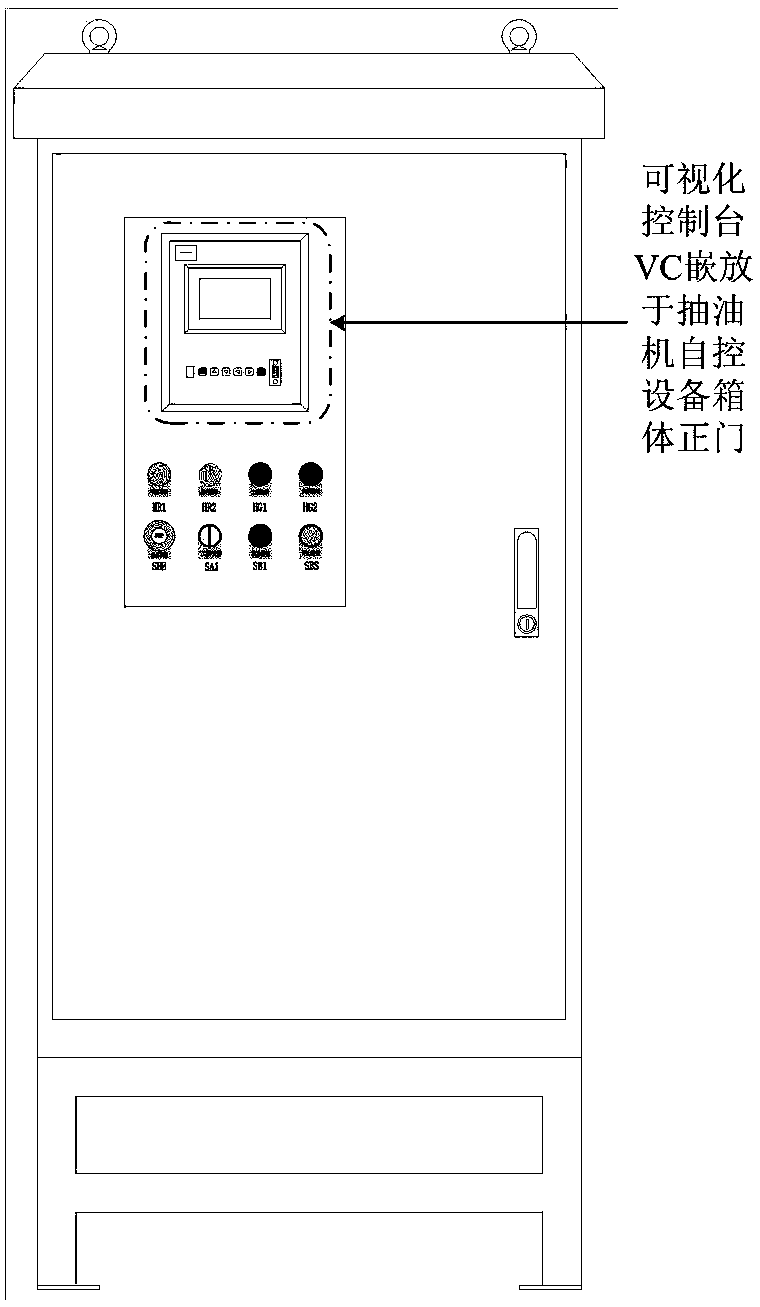
[0004] Traditional pumping unit automatic control equipment often uses simple switches, simple indicator lights and simple mechanical needle dials as operation control and operation status display, and the information it can provide is very simple, which is out of touch with the digital construction of oilfields

Method used


Image

  • Local and remote dual-purpose oil pumping unit automatic control equipment based on visual control console
  • Local and remote dual-purpose oil pumping unit automatic control equipment based on visual control console
  • Local and remote dual-purpose oil pumping unit automatic control equipment based on visual control console

Examples


Embodiment 1

[0035] Such as Figure 4 As shown, it is the display of a set of operating status parameters by the visualization console VC, which mainly includes: from top to bottom, the first line is the operating mode of the automatic control equipment, the second line is the upstream current Uab and the upstream current Iab, and the third line is the downstream voltage Uab and downlink current Iab, uplink frequency and downlink frequency in the fourth line, alarm information in the fifth line, date and hash number in the sixth line.

Embodiment 2

[0037] Such as Figure 5 As shown, it is the display of a set of operating state parameters by the visualization console VC, which mainly includes: from top to bottom, the first line is the operating mode of the automatic control equipment, the second line is the uplink active power and downlink active power, and the third line is the uplink power factor simplification. The uplink power factor and downlink power factor are simply downlink power factor, the fourth line is the current balance degree, and the power balance degree is simply the power balance, the fifth line is the alarm information, and the sixth line is the date and number.

Embodiment 3

[0039] Such as Image 6 As shown, it is the display of a set of operating state parameters by the visualization console VC, which mainly includes: from top to bottom, the first line is the operating mode of the automatic control equipment, the second line is the stroke times and running time, and the third line is the uplink power factor simplification. The uplink power factor and downlink power factor are simply downlink power factor, the fourth line is the current balance degree, and the power balance degree is simply the power balance, the fifth line is the alarm information, and the sixth line is the date and number.

[0040] Display interface embodiment four

[0041] Such as Figure 7 As shown, it is the display of a set of operating status parameters by the visualization console VC, which mainly includes: from top to bottom, the first line is the operating mode of the automatic control equipment, the second line is the daily active energy, the third line is the monthly ac...


PUM


Abstract

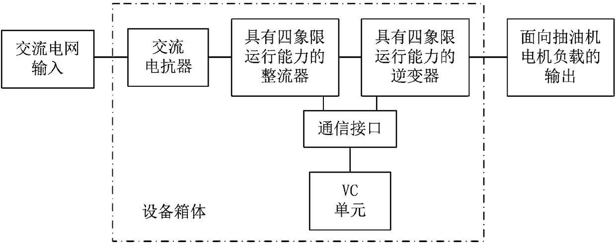
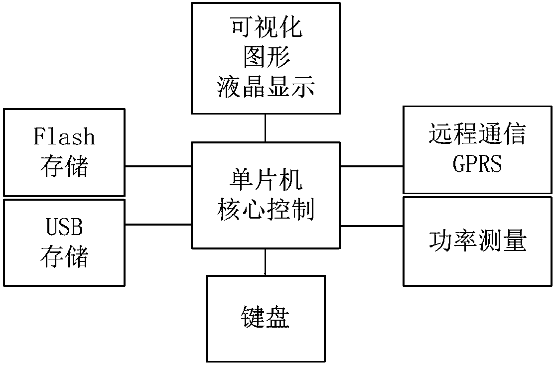
The invention discloses local and remote dual-purpose oil pumping unit automatic control equipment based on a visual control console. The local and remote dual-purpose oil pumping unit automatic control equipment is composed of an automatic control equipment box body, a visual control console VC unit, a power driving unit and a communication interface of the VC unit and the power driving unit. Theequipment can achieve local use and remote use and has the advantages of visualization, digitalization and intelligence. The VC unit adopts a single chip microcomputer as a core digital unit. The equipment further comprises a visual liquid crystal display unit, a power state measuring unit, a keyboard, a local serial communication unit facing the power unit, a flash storage unit, a USB interfaceunit and a remote GPRS communication unit facing a control center. The local and remote dual-purpose oil pumping unit automatic control equipment has the advantages of visualization, digitalization, intelligence and the like.

Description

technical field [0001] The invention relates to the field of automatic control of pumping units, in particular to a VC (Visual Console)-based automatic control device for both local and remote pumping units. Background technique [0002] Petroleum is the lifeblood of the national economy. The underground oil extraction work will use the pumping unit as the oil collection and lifting device, and the driving machine of the pumping unit often uses an AC motor. [0003] The automatic control equipment of the pumping unit can realize the automatic control of the running state of the AC motor of the pumping unit according to the given conditions. When the pumping unit automatic control equipment is only for the local pumping unit, it is the local use type automatic control equipment. The automatic control equipment of the pumping unit is only for remote telemetry and remote control, and it is a remote-use automatic control equipment. When the pumping unit automatic control equip...

Claims


Application Information

Patent Timeline
IPC IPC(8): E21B43/00G05B19/042
CPCG05B19/0423E21B43/121Y02P90/02
Inventor 康慨耿福义付艳李建霞秦兰孙晓莹纪香云
Owner 秦皇岛美城润麒自控设备有限公司
Learn More