Blade gear ring rotor air engine and circulating system

An air engine and engine cover technology, applied in the direction of rotary piston engines, rotary or swinging piston engines, engine components, etc., can solve the problems of low speed, large air consumption, and small button force, and achieve high efficiency and low air consumption. Low, high-horsepower effects

Inactive Publication Date: 2018-11-16
张谭伟
View PDF8 Cites 2 Cited by
  • Summary
  • Abstract
  • Description
  • Claims
  • Application Information

AI Technical Summary

Problems solved by technology

[0002] The air engine is a power machine for transportation, industry, electric power, etc. It is widely used in mobile equipment such as aerodynamic vehicles and air power generation. The existing vane-type air motor has a large air consumption and small button force, and the piston-type air motor has a small air consumption and low speed. ;Secondly, compressed air cannot be recycled

Method used


Image

  • Blade gear ring rotor air engine and circulating system
  • Blade gear ring rotor air engine and circulating system
  • Blade gear ring rotor air engine and circulating system

Examples


Embodiment 1

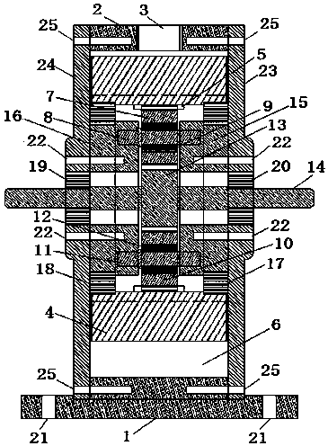
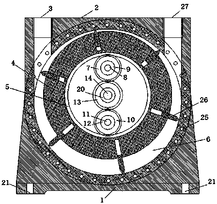
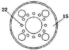
[0034] refer to Figure 1-Figure 4 , a blade ring gear rotor air engine 1, including engine casing 2, engine air inlet 3, blade ring gear rotor 4, ring gear rotor internal gear 5, cylinder 6, transmission gear I7, transmission gear shaft I8, bearing I9 , transmission gear Ⅱ10, transmission gear shaft Ⅱ11, bearing Ⅱ12, output shaft gear 13, output shaft 14, transmission gear bracket Ⅰ15, transmission gear bracket Ⅱ16, bracket bearing Ⅰ17, bracket bearing Ⅱ18, output shaft bearing Ⅰ19, output shaft bearing Ⅱ20, Machine foot screw hole 21, gear bracket screw hole 22, engine cover plate Ⅰ 23, engine cover plate Ⅱ 24, cover plate screw hole 25, blade 26, engine exhaust port 27;

[0035] The outer periphery of the blade ring gear rotor 4 is connected to the blade 26 and installed in the cylinder 6 of the engine casing 2. The transmission gear I7 is connected to the transmission gear shaft I8 through the bearing I9, and the transmission gear II10 is connected to the transmission gear...

Embodiment 2

[0042] refer to Figure 8-Figure 9 , a blade ring gear rotor air engine, the difference from Embodiment 1 is: the transmission crankshaft 30 is used to replace the transmission gear shaft I8 and the transmission gear shaft II11, and the output crankshaft 36 is used to replace the output shaft 14; the transmission crankshaft 30 is installed with Crankshaft transmission gear I28, crankshaft transmission gear II29, one end of the transmission crankshaft 30 is connected with the gear crankshaft bracket I34 through the bearing III31, and the other end is connected with the gear crankshaft bracket II35 through the bearing IV32, the crankshaft transmission gear I28, the crankshaft transmission gear II29 It meshes with the internal gear 5 of the ring gear rotor, and the transmission crankshaft 30 is connected with the output crankshaft 36 through a connecting rod 33 .

[0043] Utilizing the blade ring gear rotor air engine of the present invention can effectively solve the problem of ...


PUM


Abstract

The invention discloses a blade gear ring rotor air engine and a circulating system. The blade gear ring rotor air engine comprises an engine shell, an engine air inlet, an air cylinder, engine exhaust outlets, a blade gear ring rotor, a gear ring rotor inner gear, a transmission gear I, a transmission gear shaft I, a bearing I, a transmission gear II, a transmission gear shaft II, a bearing II, an output shaft gear, an output shaft, a transmission gear support I, a transmission gear support II, a bracket bearing I, a bracket bearing II, an output shaft bearing I, an output shaft bearing II, an engine cover plate I, an engine cover plate II and blades. The invention further provides a circulating system comprising the blade gear ring rotor air engine. The blade gear ring rotor air engine and the circulating system have the characteristics of being high in efficiency, low in air consumption, large in power, high in rotating speed and the like, and capable of being widely applied to agriculture and industrial engineering such as the power fields of transportation automobiles, ships, air-driven generators and air driven power stations.

Description

technical field [0001] The invention relates to a blade ring gear rotor air engine and a circulation system. Background technique [0002] The air engine is a power machine for transportation, industry, electric power, etc. It is widely used in mobile equipment such as aerodynamic vehicles and air power generation. The existing vane-type air motor has a large air consumption and small button force, and the piston-type air motor has a small air consumption and low speed. ; Secondly, compressed air cannot be recycled. Contents of the invention [0003] The technical problem to be solved by the present invention is to provide a blade ring gear rotor air engine with low gas consumption, high horsepower and high rotational speed. [0004] The further technical problem to be solved by the present invention is to provide a circulation system of a rotor air engine with blade ring gear with low gas consumption, high horsepower, high speed, and capable of recycling compressed air. ...

Claims


Application Information

Patent Timeline
Patent Type & Authority Applications(China)
IPC IPC(8): F01C1/344F01C17/02F01C13/04
CPCF01C1/344F01C13/04F01C17/02
Inventor 张谭伟
Owner 张谭伟
Why Eureka
Try Eureka