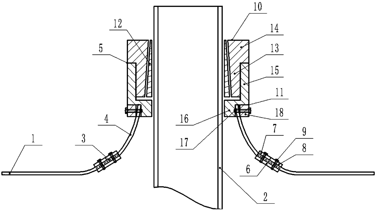
Impervious structure in position where pipe penetrates through impervious film and impervious method
An anti-seepage membrane and tube technology, which is applied in the direction of pipes, pipes/pipe joints/pipes, mechanical equipment, etc., can solve the problems of rupture of the anti-seepage membrane, failure of the anti-seepage, and leakage at the point where the pipe penetrates the anti-seepage membrane. , to achieve the effect of easy installation and reduction of anti-seepage pressure
- Summary
- Abstract
- Description
- Claims
- Application Information
AI Technical Summary
Problems solved by technology
Method used
Image
Examples
Embodiment 1
[0029] Such as figure 1As shown, the present invention is an anti-seepage structure where a pipe penetrates the anti-seepage membrane, including an anti-seepage membrane 1, a pipe 2, a flange clamp 3, a V-shaped tension anti-seepage sleeve 4 and a tube sleeve assembly 5, and the anti-seepage membrane It is an anti-seepage material made of PE film as the base material and composited with geotextiles. Its anti-seepage performance mainly depends on the PE film. The PE film used in the Oriental anti-seepage film mainly includes polyvinyl chloride, polyethylene, and EVA (ethylene / vinyl acetate copolymer). They are a kind of polymer chemical flexible material with a small specific gravity, strong extensibility, and adaptability to deformation. High, corrosion resistance, low temperature resistance, good frost resistance. The main mechanism is to block the leakage channel of the earth dam by the impermeability of the plastic film, and to withstand the water pressure and adapt to the...
Embodiment 2
[0039] Such as figure 1 As shown, a kind of anti-seepage method at the place where the pipe penetrates the anti-seepage membrane of the present invention is characterized in that it comprises the steps:
[0040] A pipeline through hole is opened on the anti-seepage membrane 1, the pipeline 2 is pierced in the pipeline through hole, and the outer ring of the flange clamp 3 is tightly clamped and connected to the anti-seepage membrane 1 corresponding to the pipeline through hole. The inner ring of the flange clamp 3 is sealed and clamped to the large end of the V-shaped tensioned anti-seepage sleeve 4, and the small end of the V-shaped tensioned anti-seepage sleeve 4 is sealed and clamped to connect to the tube sleeve assembly 4. The pipe sleeve assembly 4 is tightly sleeved and connected to the pipe 2 corresponding to the pipe through hole.
[0041] The pipe sleeve assembly 5 includes an upper pipe joint 10, a lower pipe joint 11 and a sealing ring 12, and the upper pipe joint...
PUM
 Abstract
Description
Claims
Application Information
 - R&D
- Intellectual Property
- Life Sciences
- Materials
- Tech Scout
- Unparalleled Data Quality
- Higher Quality Content
- 60% Fewer Hallucinations
Browse by: Latest US Patents, China's latest patents, Technical Efficacy Thesaurus, Application Domain, Technology Topic, Popular Technical Reports.
© 2025 PatSnap. All rights reserved.Legal|Privacy policy|Modern Slavery Act Transparency Statement|Sitemap|About US| Contact US: help@patsnap.com

